 |
Electronic Components Datasheet Search |
|
|
Electronic Components Datasheet Search |
|
The question interval is too short.
Please try again in a few seconds.

Hello, Please ask a question about W5PA-A24BA2-R2/Q Datasheet
# Example questions:
➢ What are the power consumption specifications for both ac and dc operation of the w5pa?
➢ What are the available options for terminal screw material, as indicated by the option codes?
➢ What are the frequency range limitations for mechanical contact inputs?
| Part No. | W5PA-A24BA2-R2/Q |
| Manufacturer | MSYSTEM |
| Size | 114 Kbytes |
| Pages | 3 pages |
| Description | Terminal Block Dual Output Signal Conditioners W5-UNIT |


1. Overview & Ordering Information
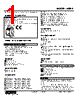
️· Product: M-System W5PA Signal Conditioner
️· Model Number Format: `W5PA-[1][2][3][4]-[5][6]` - Each bracket represents a configurable option.
️· Ordering Instructions: Specify a code from the listed options for each bracket (e.g., `W5PA-A144W4W-R/Q`).
️· Additional Ordering Notes: You can specify a frequency range (e.g., 0-1 kHz), a special output range (using codes 'Z' and '0'), and any options selected under the `/Q` code (e.g., /C01/S01).
2. Configurable Options (Code Breakdown)
Let's detail what each bracketed code represents:
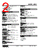
️· [1] Input Type:
- `A1`: Open Collector
- `A2`: Mechanical Contact
- `C`: 5V Pulse (sensitivity 2V)
- `D`: 12V/24V Pulse (sensitivity 5V)
️· [2] Excitation Voltage:
- `4`: 12V DC / 30mA
- `7`: 24V DC / 12mA
️· [3] Output 1 Type (Current):
- `A`: 4–20 mA DC (load resistance 550 Ω max)
- `B`: 2–10 mA DC (load resistance 1100 Ω max)
- `C`: 1–5 mA DC (load resistance 2200 Ω max)
- `D`: 0–20 mA DC (load resistance 550 Ω max)
- `E`: 0–16 mA DC (load resistance 685 Ω max)
- `F`: 0–10 mA DC (load resistance 1100 Ω max)
- `G`: 0–1 mA DC (load resistance 11 kΩ max)
- `Z`: Specify current (see output specifications)
️· [4] Output 1 Type (Voltage):
- '4': Specify voltage (See output specifications)
️· [5] Options:
- `blank`: No options
- `/Q`: With options (requires specification of additional codes)
■ `/C01`: Silicone coating
■ `/C02`: Polyurethane coating
■ `/C03`: Rubber coating
■ `/S01`: Stainless steel terminal screws
️· [6] Special Options:
- '0': Special output ranges
- `R`: Frequency range (e.g., 0 – 1 kHz)
3. Technical Specifications
️· General:
- Construction: Terminal block
- Input Terminals: M3.5 screw terminals (0.8 N·m torque)
- Output/Power Terminals: M3 screw terminals (0.8 N·m torque)
- Terminal Material: Nickel-plated steel (standard) or stainless steel (option)
- Housing: Flame-resistant resin (black)
- Isolation: Input to output 1, output 2, and power
️· Performance:
- Overrange Output: -10 to +120% at 1-5 V
- Zero Adjustment: -2 to +2% (or ±1% with code 4W/5W)
- Span Adjustment: 98 to 102% (or 99 to 101% with code 4W/5W)
️· Input Specifications:
- Open Collector: Frequency range 0-100 kHz
- Mechanical Contact: Frequency range 0-30 Hz
- Voltage Pulse: Frequency range 0-100 kHz; waveform: square or sine; input impedance ≥ 10 kΩ; voltage sensitivity: 2V (5V pulse), 5V (12V/24V pulse)
- Short-circuit protection for 12V/24V excitation.
️· Output Specifications:
- DC Current Output: 0-20 mA; minimum span: 1 mA; load resistance up to 11 kΩ.
- DC Voltage Output: -10 - +12V; minimum span: 5 mV; load resistance up to 11 kΩ
️· Power Consumption:
- AC: 6–8 VA
- DC: 3 W
️· Environmental:
- Operating Temperature: -5 to +55°C
- Operating Humidity: 0 to 90% RH
️· Standards: RoHS Directive, EMC Directive.
4. Connections & Schematic
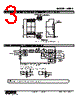
️· The device has a schematic diagram showing the signal flow: Sensor Excitation → Input → Waveform Shaper → Digital Computation → Voltage Amplifier → Output 1 & Output 2.
️· Important Notes:
- The schematic illustrates the 2nd output option.
- Do not connect to terminals 1 & 2.
5. Important Cautions
️· Input Frequency Limit: The W5PA is designed to handle frequencies up to 100 kHz, but excessive chattering can occur above certain frequencies. A filter circuit is built in to reduce chatter with mechanical contacts, but an external filter might be needed in some situations.
️· Mounting: Allow sufficient space around the unit.
1. Overview & Ordering Information
️· Product: M-System W5PA Signal Conditioner
️· Model Number Format: `W5PA-[1][2][3][4]-[5][6]` - Each bracket represents a configurable option.
️· Ordering Instructions: Specify a code from the listed options for each bracket (e.g., `W5PA-A144W4W-R/Q`).
️· Additional Ordering Notes: You can specify a frequency range (e.g., 0-1 kHz), a special output range (using codes 'Z' and '0'), and any options selected under the `/Q` code (e.g., /C01/S01).
2. Configurable Options (Code Breakdown)
Let's detail what each bracketed code represents:
️· [1] Input Type:
- `A1`: Open Collector
- `A2`: Mechanical Contact
- `C`: 5V Pulse (sensitivity 2V)
- `D`: 12V/24V Pulse (sensitivity 5V)
️· [2] Excitation Voltage:
- `4`: 12V DC / 30mA
- `7`: 24V DC / 12mA
️· [3] Output 1 Type (Current):
- `A`: 4–20 mA DC (load resistance 550 Ω max)
- `B`: 2–10 mA DC (load resistance 1100 Ω max)
- `C`: 1–5 mA DC (load resistance 2200 Ω max)
- `D`: 0–20 mA DC (load resistance 550 Ω max)
- `E`: 0–16 mA DC (load resistance 685 Ω max)
- `F`: 0–10 mA DC (load resistance 1100 Ω max)
- `G`: 0–1 mA DC (load resistance 11 kΩ max)
- `Z`: Specify current (see output specifications)
️· [4] Output 1 Type (Voltage):
- '4': Specify voltage (See output specifications)
️· [5] Options:
- `blank`: No options
- `/Q`: With options (requires specification of additional codes)
■ `/C01`: Silicone coating
■ `/C02`: Polyurethane coating
■ `/C03`: Rubber coating
■ `/S01`: Stainless steel terminal screws
️· [6] Special Options:
- '0': Special output ranges
- `R`: Frequency range (e.g., 0 – 1 kHz)
3. Technical Specifications
️· General:
- Construction: Terminal block
- Input Terminals: M3.5 screw terminals (0.8 N·m torque)
- Output/Power Terminals: M3 screw terminals (0.8 N·m torque)
- Terminal Material: Nickel-plated steel (standard) or stainless steel (option)
- Housing: Flame-resistant resin (black)
- Isolation: Input to output 1, output 2, and power
️· Performance:
- Overrange Output: -10 to +120% at 1-5 V
- Zero Adjustment: -2 to +2% (or ±1% with code 4W/5W)
- Span Adjustment: 98 to 102% (or 99 to 101% with code 4W/5W)
️· Input Specifications:
- Open Collector: Frequency range 0-100 kHz
- Mechanical Contact: Frequency range 0-30 Hz
- Voltage Pulse: Frequency range 0-100 kHz; waveform: square or sine; input impedance ≥ 10 kΩ; voltage sensitivity: 2V (5V pulse), 5V (12V/24V pulse)
- Short-circuit protection for 12V/24V excitation.
️· Output Specifications:
- DC Current Output: 0-20 mA; minimum span: 1 mA; load resistance up to 11 kΩ.
- DC Voltage Output: -10 - +12V; minimum span: 5 mV; load resistance up to 11 kΩ
️· Power Consumption:
- AC: 6–8 VA
- DC: 3 W
️· Environmental:
- Operating Temperature: -5 to +55°C
- Operating Humidity: 0 to 90% RH
️· Standards: RoHS Directive, EMC Directive.
4. Connections & Schematic
️· The device has a schematic diagram showing the signal flow: Sensor Excitation → Input → Waveform Shaper → Digital Computation → Voltage Amplifier → Output 1 & Output 2.
️· Important Notes:
- The schematic illustrates the 2nd output option.
- Do not connect to terminals 1 & 2.
5. Important Cautions
️· Input Frequency Limit: The W5PA is designed to handle frequencies up to 100 kHz, but excessive chattering can occur above certain frequencies. A filter circuit is built in to reduce chatter with mechanical contacts, but an external filter might be needed in some situations.
️· Mounting: Allow sufficient space around the unit.
| Part No. | W5PA-A24BA2-R2/Q |
| Manufacturer | MSYSTEM |
| Size | 114 Kbytes |
| Pages | 3 pages |
| Description | Terminal Block Dual Output Signal Conditioners W5-UNIT |
| Does ALLDATASHEET help your business so far? [ DONATE ] |
About Alldatasheet | Advertisement | Contact us | Privacy Policy | Link to Datasheet | Link Exchange | Manufacturer List All Rights Reserved©Alldatasheet.com |
| Russian : Alldatasheetru.com | Korean : Alldatasheet.co.kr | Spanish : Alldatasheet.es | French : Alldatasheet.fr | Italian : Alldatasheetit.com Portuguese : Alldatasheetpt.com | Polish : Alldatasheet.pl | Vietnamese : Alldatasheet.vn Indian : Alldatasheet.in | Mexican : Alldatasheet.com.mx | British : Alldatasheet.co.uk | New Zealand : Alldatasheet.co.nz |
|
Family Site : ic2ic.com |
icmetro.com |
 New Zealand ▼
  English
 Chinese
 German
 Japanese
 Russian
 Korean
 Spanish
 French
 Italian
 Portuguese
 Polish
 Vietnamese
 Indian
 Mexican
 British