 |
Electronic Components Datasheet Search |
|
|
Electronic Components Datasheet Search |
|
The question interval is too short.
Please try again in a few seconds.

Hello, Please ask a question about KEPFU-122P2-V/Q Datasheet
# Example questions:
➢ What are the available output signal options for the kepfu transducer, and what is the typical accuracy of those signals?
➢ What type of mounting is supported for the kepfu (e.g., din rail, panel mount), and what are the dimensions of the unit to ensure proper installation space?
➢ What is the purpose of this protector, and is it included with the kepfu transducer, or is it a separate purchase?
| Part No. | KEPFU-122P2-V/Q |
| Manufacturer | MSYSTEM |
| Size | 130 Kbytes |
| Pages | 4 pages |
| Description | Plug-in Signal Conditioners K-UNIT |

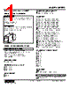
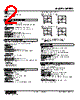

1. Product Overview: KEPFU - AC Voltage Transducer
️· What it is: The KEPFU is an AC voltage transducer. It converts AC voltage signals into standard output signals (typically 4-20mA or 0-10V DC). It's designed for industrial applications where voltage measurement and signal transmission are required.
️· Isolation: It provides galvanic isolation between the input and output circuits, enhancing safety and reducing noise.
️· Power Options: It can be powered from either the input voltage (auto-ranging) or an external DC power supply (24V DC).
️· CT Protector Compatibility: It's compatible with M-System's CT Protector (model CTM) for overload protection.
2. Ordering Information & Specifications
️· Model Numbers: The datasheet doesn't explicitly list model numbers, but the document seems to refer to different output signal options (4-20mA, 0-10V). You'd need to consult M-System's full catalog for specific model designations.
️· Input Voltage Range: The datasheet does not provide a specific input voltage range. You would need to check the model-specific specifications in a more detailed catalog.
️· Output Signals:
- 4-20mA DC (standard) – Isolated
- 0-10V DC (standard) – Isolated
️· Burden: The maximum load resistance for the output signal is also not specified and would need to be found in model-specific documentation.
️· Accuracy: The accuracy is not given directly.
️· Operating Temperature: Not listed, check model specific sheets.
️· Storage Temperature: Not listed, check model specific sheets.
️· Humidity: Not listed, check model specific sheets.
3. Electrical Connections & Terminal Assignments
️· Input Terminals: Not clearly defined.
️· Output Terminals: Clearly identified for 4-20mA and 0-10V outputs. These terminals are used for connecting the load resistance.
️· Power Terminals: For external power supply.
️· CT Protector Terminals: For connecting the optional CT Protector.
️· Terminal Diagrams: The terminal diagrams (towards the bottom of page 3) are crucial for proper wiring. They show the layout of the terminals for input, output, and power connections.
4. Mechanical Dimensions & Mounting
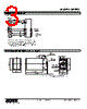
️· DIN Rail Mounting: Designed for standard 35mm DIN rail mounting.
️· Dimensions: The diagram shows the dimensions, including height, width, and depth (approximately 103x132x20 mm).
️· Mounting Notes: No extra space is needed between units when mounting.
️· Mounting Hole Details: Show details of the mounting holes and screw specifications (11-M3.5).
5. Key Notes and Important Considerations
️· Auto-Ranging Power: The transducer can be powered from the input voltage.
️· CT Protector: The use of the CT Protector is recommended for enhanced safety.
️· Wiring: Pay close attention to the terminal diagrams.
️· Burden Resistance: Consider the load resistance when connecting the output signal.
️· Model-Specific Data: The datasheet provides a general overview. For precise specifications (input voltage range, accuracy, etc.), you *must* consult the datasheet for the specific KEPFU model you intend to use.
️· Consult M-System Documentation: The best reference is M-System's full catalog and datasheet for the specific KEPFU model.
1. Product Overview: KEPFU - AC Voltage Transducer
️· What it is: The KEPFU is an AC voltage transducer. It converts AC voltage signals into standard output signals (typically 4-20mA or 0-10V DC). It's designed for industrial applications where voltage measurement and signal transmission are required.
️· Isolation: It provides galvanic isolation between the input and output circuits, enhancing safety and reducing noise.
️· Power Options: It can be powered from either the input voltage (auto-ranging) or an external DC power supply (24V DC).
️· CT Protector Compatibility: It's compatible with M-System's CT Protector (model CTM) for overload protection.
2. Ordering Information & Specifications
️· Model Numbers: The datasheet doesn't explicitly list model numbers, but the document seems to refer to different output signal options (4-20mA, 0-10V). You'd need to consult M-System's full catalog for specific model designations.
️· Input Voltage Range: The datasheet does not provide a specific input voltage range. You would need to check the model-specific specifications in a more detailed catalog.
️· Output Signals:
- 4-20mA DC (standard) – Isolated
- 0-10V DC (standard) – Isolated
️· Burden: The maximum load resistance for the output signal is also not specified and would need to be found in model-specific documentation.
️· Accuracy: The accuracy is not given directly.
️· Operating Temperature: Not listed, check model specific sheets.
️· Storage Temperature: Not listed, check model specific sheets.
️· Humidity: Not listed, check model specific sheets.
3. Electrical Connections & Terminal Assignments
️· Input Terminals: Not clearly defined.
️· Output Terminals: Clearly identified for 4-20mA and 0-10V outputs. These terminals are used for connecting the load resistance.
️· Power Terminals: For external power supply.
️· CT Protector Terminals: For connecting the optional CT Protector.
️· Terminal Diagrams: The terminal diagrams (towards the bottom of page 3) are crucial for proper wiring. They show the layout of the terminals for input, output, and power connections.
4. Mechanical Dimensions & Mounting
️· DIN Rail Mounting: Designed for standard 35mm DIN rail mounting.
️· Dimensions: The diagram shows the dimensions, including height, width, and depth (approximately 103x132x20 mm).
️· Mounting Notes: No extra space is needed between units when mounting.
️· Mounting Hole Details: Show details of the mounting holes and screw specifications (11-M3.5).
5. Key Notes and Important Considerations
️· Auto-Ranging Power: The transducer can be powered from the input voltage.
️· CT Protector: The use of the CT Protector is recommended for enhanced safety.
️· Wiring: Pay close attention to the terminal diagrams.
️· Burden Resistance: Consider the load resistance when connecting the output signal.
️· Model-Specific Data: The datasheet provides a general overview. For precise specifications (input voltage range, accuracy, etc.), you *must* consult the datasheet for the specific KEPFU model you intend to use.
️· Consult M-System Documentation: The best reference is M-System's full catalog and datasheet for the specific KEPFU model.
| Part No. | KEPFU-122P2-V/Q |
| Manufacturer | MSYSTEM |
| Size | 130 Kbytes |
| Pages | 4 pages |
| Description | Plug-in Signal Conditioners K-UNIT |
| Does ALLDATASHEET help your business so far? [ DONATE ] |
About Alldatasheet | Advertisement | Contact us | Privacy Policy | Link to Datasheet | Link Exchange | Manufacturer List All Rights Reserved©Alldatasheet.com |
| Russian : Alldatasheetru.com | Korean : Alldatasheet.co.kr | Spanish : Alldatasheet.es | French : Alldatasheet.fr | Italian : Alldatasheetit.com Portuguese : Alldatasheetpt.com | Polish : Alldatasheet.pl | Vietnamese : Alldatasheet.vn Indian : Alldatasheet.in | Mexican : Alldatasheet.com.mx | British : Alldatasheet.co.uk | New Zealand : Alldatasheet.co.nz |
|
Family Site : ic2ic.com |
icmetro.com |
 New Zealand ▼
  English
 Chinese
 German
 Japanese
 Russian
 Korean
 Spanish
 French
 Italian
 Portuguese
 Polish
 Vietnamese
 Indian
 Mexican
 British