 |
Electronic Components Datasheet Search |
|
|
Electronic Components Datasheet Search |
|
The question interval is too short.
Please try again in a few seconds.

Hello, Please ask a question about AX88140AP Datasheet
# Example questions:
➢ Explain the relationship between 'irdy#' and 'trdy#' in completing a data phase of a pci bus transaction, according to the documentation.
➢ What is the function of the 'frame#' signal during a pci bus transaction?
➢ The document lists several signals that *must* be pulled up by an external resistor. name three of these signals.
| Part No. | AX88140AP |
| Manufacturer | ASIX |
| Size | 467 Kbytes |
| Pages | 46 pages |
| Description | Fast Ethernet MAC Controller |








Okay, I'm ready to summarize the provided text. Here's a breakdown of the key information contained within it:
Overall Context:
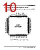
The document describes the PCI interface signals for the AX88140A device (likely a network adapter or similar peripheral). It outlines the function of various pins and signals involved in communication with the PCI bus.
Key Sections & Highlights:
️· PCI Interface Signals: The bulk of the document is a table listing PCI interface signals, their pin assignments (for two different board layouts, likely), and a description of their function. This table is divided into a PCI interface group.
️· Signal Categories & Functions:
- Address/Data: Signals like `AD[31:0]` are multiplexed and carry either address or data depending on the phase of the PCI transaction.
- Byte Enables (CBE#): Control which bytes of data are valid during a transaction.
- Control Signals: Signals like `FRAME#`, `GNT#`, `REQ#`, `STOP#` govern bus access and the flow of data.
- Error Signals: `PERR#` (parity error), `SERR#` (system error) indicate errors during transactions.
- Reset: `RST#` resets the device.
- Clock: `PCI_CLK` provides the timing for PCI operations.
️· Important Considerations:
- Pin Assignments: Pin numbers vary depending on the board version (two different layouts described).
- External Resistors: Some signals (e.g., `INT#`, `PERR#`) require external pull-up resistors.
- Endianness: The device supports both little-endian and big-endian byte ordering.
- Timing: The PCI clock frequency must be within the range of 21MHz to 33MHz.
- Multiplexing: Address and data signals are multiplexed on the same pins.
In essence, the text serves as a technical reference for integrating the AX88140A device onto a PCI bus, detailing the necessary signals and their behavior.
Overall Context:
The document describes the PCI interface signals for the AX88140A device (likely a network adapter or similar peripheral). It outlines the function of various pins and signals involved in communication with the PCI bus.
Key Sections & Highlights:
️· PCI Interface Signals: The bulk of the document is a table listing PCI interface signals, their pin assignments (for two different board layouts, likely), and a description of their function. This table is divided into a PCI interface group.
️· Signal Categories & Functions:
- Address/Data: Signals like `AD[31:0]` are multiplexed and carry either address or data depending on the phase of the PCI transaction.
- Byte Enables (CBE#): Control which bytes of data are valid during a transaction.
- Control Signals: Signals like `FRAME#`, `GNT#`, `REQ#`, `STOP#` govern bus access and the flow of data.
- Error Signals: `PERR#` (parity error), `SERR#` (system error) indicate errors during transactions.
- Reset: `RST#` resets the device.
- Clock: `PCI_CLK` provides the timing for PCI operations.
️· Important Considerations:
- Pin Assignments: Pin numbers vary depending on the board version (two different layouts described).
- External Resistors: Some signals (e.g., `INT#`, `PERR#`) require external pull-up resistors.
- Endianness: The device supports both little-endian and big-endian byte ordering.
- Timing: The PCI clock frequency must be within the range of 21MHz to 33MHz.
- Multiplexing: Address and data signals are multiplexed on the same pins.
In essence, the text serves as a technical reference for integrating the AX88140A device onto a PCI bus, detailing the necessary signals and their behavior.
| Part No. | AX88140AP |
| Manufacturer | ASIX |
| Size | 467 Kbytes |
| Pages | 46 pages |
| Description | Fast Ethernet MAC Controller |
| Does ALLDATASHEET help your business so far? [ DONATE ] |
About Alldatasheet | Advertisement | Contact us | Privacy Policy | Link to Datasheet | Link Exchange | Manufacturer List All Rights Reserved©Alldatasheet.com |
| Russian : Alldatasheetru.com | Korean : Alldatasheet.co.kr | Spanish : Alldatasheet.es | French : Alldatasheet.fr | Italian : Alldatasheetit.com Portuguese : Alldatasheetpt.com | Polish : Alldatasheet.pl | Vietnamese : Alldatasheet.vn Indian : Alldatasheet.in | Mexican : Alldatasheet.com.mx | British : Alldatasheet.co.uk | New Zealand : Alldatasheet.co.nz |
|
Family Site : ic2ic.com |
icmetro.com |
 New Zealand ▼
  English
 Chinese
 German
 Japanese
 Russian
 Korean
 Spanish
 French
 Italian
 Portuguese
 Polish
 Vietnamese
 Indian
 Mexican
 British