 |
Electronic Components Datasheet Search |
|
|
Electronic Components Datasheet Search |
|
The question interval is too short.
Please try again in a few seconds.

Hello, Please ask a question about BFP182R_14 Datasheet
# Example questions:
➢ What is the maximum stable power gain at 900 mhz, and what parameters define this gain (e.g., bias conditions, impedance matching)?
➢ At what frequency does the collector-base capacitance reach 0.4 pf, according to the datasheet?
➢ What is the minimum noise figure of this transistor at 900 mhz, and what are the conditions required to achieve this value?
| Part No. | BFP182R_14 |
| Manufacturer | INFINEON |
| Size | 556 Kbytes |
| Pages | 6 pages |
| Description | Low Noise Silicon Bipolar RF Transistor |

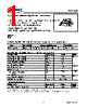
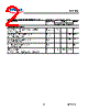
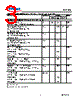
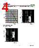


1. Device Overview & Identification:
️· Device: BJT (Bipolar Junction Transistor)
️· Manufacturer: Infineon Technologies
️· Datasheet Edition: 2009-11-16
️· Part Number (implied): The datasheet doesn't explicitly state the part number, but this is likely a datasheet for a general BJT device.
2. Electrical Characteristics:
️· AC Characteristics:
- Transition Frequency (fT): 6-8 GHz at 15mA, 8V. (Indicates the high-frequency performance)
- Collector-Base Capacitance (Ccb): 0.25-0.4 pF (Important for high-frequency circuit design).
- Collector-Emitter Capacitance (Cce): 0.3 pF (Also key for high-frequency performance).
- Emitter-Base Capacitance (Cbe): 0.8 pF (Another important capacitor for frequency response).
️· Noise Figure:
- 0.9 dB at 3mA, 6V, optimized load (Z_Sopt) at 900MHz.
- 1.3 dB at 3mA, 6V, optimized load (Z_Sopt) at 1.8GHz.
️· Gain:
- Maximum Stable Gain (Gms): 22 dB at 900MHz
- Maximum Available Gain (Gma): 16.5 dB at 1.8 GHz
️· Capacitance:
- Collector-base capacitance (Ccb): 0.25-0.4 pF
- Collector emitter capacitance (Cce): 0.3 pF
- Emitter-base capacitance (Cbe): 0.8 pF
3. DC Characteristics (Not Fully Listed, but implied):
️· The datasheet doesn't provide a full DC characteristics table (Vce, Ic, etc.). However, the values mentioned (Vce = 8V, Ic = 15mA, Ic = 3mA) suggest typical operating conditions.
4. Power Dissipation and Thermal Considerations:
️· Total Power Dissipation (Ptot): A graph shows Ptot as a function of junction temperature (Ts). This indicates the maximum power that can be safely dissipated by the device.
️· Thermal Resistance (RthJS): A graph shows RthJS as a function of pulse width. This is crucial for determining safe operating conditions under pulsed loads.
5. Operating Conditions & Load Impedance:
️· Optimized Load Impedance (Zsopt): The noise figure measurements indicate the device has an "optimized load" for minimum noise. This suggests the device is designed to be used with specific biasing and/or impedance matching.
️· Typical Operating Voltages/Currents: Vce = 8V, Ic = 15mA, Ic = 3mA are indicated.
6. Important Notes & Definitions:
️· Gms (Maximum Stable Gain): The maximum power gain achievable without oscillation.
️· Gma (Maximum Available Gain): The highest gain obtainable with proper load matching.
️· Zsopt: The source impedance for minimizing noise figure.
️· RthJS: Thermal resistance from junction to case. Used for calculating maximum allowable junction temperature.
Overall Key Takeaways:
️· High-Frequency Performance: The transistor is designed for reasonably high-frequency applications, given the fT and capacitance values.
️· Noise Figure: It's a low-noise transistor when operated within the specified conditions.
️· Thermal Management: Careful attention must be paid to thermal management, especially under pulsed operating conditions. The junction temperature must be kept within limits.
️· Load Matching: To achieve best performance (low noise, maximum gain), load impedance matching is likely necessary.
️· Missing Information: The datasheet doesn't provide a complete DC characterization, meaning key information like collector current rating, voltage ratings, and current gain (hFE) are not given.
1. Device Overview & Identification:
️· Device: BJT (Bipolar Junction Transistor)
️· Manufacturer: Infineon Technologies
️· Datasheet Edition: 2009-11-16
️· Part Number (implied): The datasheet doesn't explicitly state the part number, but this is likely a datasheet for a general BJT device.
2. Electrical Characteristics:
️· AC Characteristics:
- Transition Frequency (fT): 6-8 GHz at 15mA, 8V. (Indicates the high-frequency performance)
- Collector-Base Capacitance (Ccb): 0.25-0.4 pF (Important for high-frequency circuit design).
- Collector-Emitter Capacitance (Cce): 0.3 pF (Also key for high-frequency performance).
- Emitter-Base Capacitance (Cbe): 0.8 pF (Another important capacitor for frequency response).
️· Noise Figure:
- 0.9 dB at 3mA, 6V, optimized load (Z_Sopt) at 900MHz.
- 1.3 dB at 3mA, 6V, optimized load (Z_Sopt) at 1.8GHz.
️· Gain:
- Maximum Stable Gain (Gms): 22 dB at 900MHz
- Maximum Available Gain (Gma): 16.5 dB at 1.8 GHz
️· Capacitance:
- Collector-base capacitance (Ccb): 0.25-0.4 pF
- Collector emitter capacitance (Cce): 0.3 pF
- Emitter-base capacitance (Cbe): 0.8 pF
3. DC Characteristics (Not Fully Listed, but implied):
️· The datasheet doesn't provide a full DC characteristics table (Vce, Ic, etc.). However, the values mentioned (Vce = 8V, Ic = 15mA, Ic = 3mA) suggest typical operating conditions.
4. Power Dissipation and Thermal Considerations:
️· Total Power Dissipation (Ptot): A graph shows Ptot as a function of junction temperature (Ts). This indicates the maximum power that can be safely dissipated by the device.
️· Thermal Resistance (RthJS): A graph shows RthJS as a function of pulse width. This is crucial for determining safe operating conditions under pulsed loads.
5. Operating Conditions & Load Impedance:
️· Optimized Load Impedance (Zsopt): The noise figure measurements indicate the device has an "optimized load" for minimum noise. This suggests the device is designed to be used with specific biasing and/or impedance matching.
️· Typical Operating Voltages/Currents: Vce = 8V, Ic = 15mA, Ic = 3mA are indicated.
6. Important Notes & Definitions:
️· Gms (Maximum Stable Gain): The maximum power gain achievable without oscillation.
️· Gma (Maximum Available Gain): The highest gain obtainable with proper load matching.
️· Zsopt: The source impedance for minimizing noise figure.
️· RthJS: Thermal resistance from junction to case. Used for calculating maximum allowable junction temperature.
Overall Key Takeaways:
️· High-Frequency Performance: The transistor is designed for reasonably high-frequency applications, given the fT and capacitance values.
️· Noise Figure: It's a low-noise transistor when operated within the specified conditions.
️· Thermal Management: Careful attention must be paid to thermal management, especially under pulsed operating conditions. The junction temperature must be kept within limits.
️· Load Matching: To achieve best performance (low noise, maximum gain), load impedance matching is likely necessary.
️· Missing Information: The datasheet doesn't provide a complete DC characterization, meaning key information like collector current rating, voltage ratings, and current gain (hFE) are not given.
| Part No. | BFP182R_14 |
| Manufacturer | INFINEON |
| Size | 556 Kbytes |
| Pages | 6 pages |
| Description | Low Noise Silicon Bipolar RF Transistor |
| Does ALLDATASHEET help your business so far? [ DONATE ] |
About Alldatasheet | Advertisement | Contact us | Privacy Policy | Link to Datasheet | Link Exchange | Manufacturer List All Rights Reserved©Alldatasheet.com |
| Russian : Alldatasheetru.com | Korean : Alldatasheet.co.kr | Spanish : Alldatasheet.es | French : Alldatasheet.fr | Italian : Alldatasheetit.com Portuguese : Alldatasheetpt.com | Polish : Alldatasheet.pl | Vietnamese : Alldatasheet.vn Indian : Alldatasheet.in | Mexican : Alldatasheet.com.mx | British : Alldatasheet.co.uk | New Zealand : Alldatasheet.co.nz |
|
Family Site : ic2ic.com |
icmetro.com |
 New Zealand ▼
  English
 Chinese
 German
 Japanese
 Russian
 Korean
 Spanish
 French
 Italian
 Portuguese
 Polish
 Vietnamese
 Indian
 Mexican
 British