|
Electronic Components Datasheet Search |
|
|
Electronic Components Datasheet Search |
|
STM32G47PBY6XXX Datasheet(PDF) 125 Page - STMicroelectronics |
|
|
|||||||||||||||||||||||||||||
STM32G47PBY6XXX Datasheet(HTML) 125 Page - STMicroelectronics |
|
|
125 / 229 page 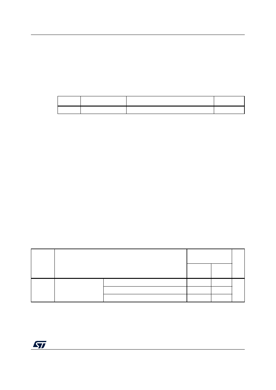 DS12712 Rev 3 125/229 STM32G473xB STM32G473xC STM32G473xE Electrical characteristics 194 Static latch-up Two complementary static tests are required on three parts to assess the latch-up performance: • A supply overvoltage is applied to each power supply pin. • A current injection is applied to each input, output and configurable I/O pin. These tests are compliant with EIA/JESD 78E IC latch-up standard. 5.3.13 I/O current injection characteristics As a general rule, current injection to the I/O pins, due to external voltage below VSS or above VDD (for standard, 3.3 V-capable I/O pins) should be avoided during normal product operation. However, in order to give an indication of the robustness of the microcontroller in cases when abnormal injection accidentally happens, susceptibility tests are performed on a sample basis during device characterization. Functional susceptibility to I/O current injection While a simple application is executed on the device, the device is stressed by injecting current into the I/O pins programmed in floating input mode. While current is injected into the I/O pin, one at a time, the device is checked for functional failures. The failure is indicated by an out of range parameter: ADC error above a certain limit (higher than 5 LSB TUE), out of conventional limits of induced leakage current on adjacent pins (out of the -5 µA/+0 µA range) or other functional failure (for example reset occurrence or oscillator frequency deviation). The characterization results are given in Table 53. Negative induced leakage current is caused by negative injection and positive induced leakage current is caused by positive injection. Table 52. Electrical sensitivities Symbol Parameter Conditions Class LU Static latch-up class TA = +125 °C conforming to JESD78E Class II level A Table 53. I/O current injection susceptibility Symbol Description Functional susceptibility Unit Negative injection Positive injection IINJ(1) Injected current on pin All except TT_a, PF10, PB8-BOOT0, PC10 -5 NA mA PF10, PB8-BOOT0, PC10 -0 NA TT_a pins -5 0 1. Guaranteed by characterization. |
|
Link URL |
| Does ALLDATASHEET help your business so far? [ DONATE ] |
About Alldatasheet | Advertisement | Contact us | Privacy Policy | Link to Datasheet | Link Exchange | Manufacturer List All Rights Reserved©Alldatasheet.com |
| Russian : Alldatasheetru.com | Korean : Alldatasheet.co.kr | Spanish : Alldatasheet.es | French : Alldatasheet.fr | Italian : Alldatasheetit.com Portuguese : Alldatasheetpt.com | Polish : Alldatasheet.pl | Vietnamese : Alldatasheet.vn Indian : Alldatasheet.in | Mexican : Alldatasheet.com.mx | British : Alldatasheet.co.uk | New Zealand : Alldatasheet.co.nz |
|
Family Site : ic2ic.com |
icmetro.com |
 New Zealand ▼
 English
 Chinese
 German
 Japanese
 Russian
 Korean
 Spanish
 French
 Italian
 Portuguese
 Polish
 Vietnamese
 Indian
 Mexican
 British
 New Zealand