 |
Electronic Components Datasheet Search |
|
|
Electronic Components Datasheet Search |
|
The question interval is too short.
Please try again in a few seconds.

Hello, Please ask a question about IRDCIP1001-B Datasheet
# Example questions:
➢ Explain in brief how equation 1 is used, and what components are needed to implement it.
➢ What is the purpose of resistor r7 and how does its value affect the circuit's operation?
➢ What type of capacitor is specified for c1 through c10?
| Part No. | IRDCIP1001-B |
| Manufacturer | IRF |
| Size | 586 Kbytes |
| Pages | 6 pages |
| Description | 200kHz to 300kHz, 20A, 5VIN to 12VIN Single Phase Synchronous Buck Converter using iP1001 |




1. Project Overview:
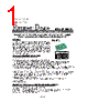
️· Product: IRDCiP1001-B is a power block (likely a power management IC) from International Rectifier (now part of Infineon). It's designed for applications needing a compact and integrated power solution.
️· Reference Design: This document provides a complete reference design for utilizing the IRDCiP1001-B. This includes schematics, component placement diagrams, and a detailed bill of materials (BOM).
️· Purpose: The design aims to demonstrate how to implement the IRDCiP1001-B effectively in a real-world application.
2. Key Design Features & Components:
️· Operating Range: Designed for input voltages from 5V to 12V.
️· Bill of Materials (BOM): A complete list of components, including:
- Capacitors (C1-C16) – Various values, voltage ratings, and types (X5R, X7R, Tantalum).
- Schottky Diode (D1) – For rectification and protection.
- Inductor (L1 & L2) – L1 is specifically used, L2 is not populated.
- Resistors (R1-R7) – Various values for current limiting and voltage adjustment.
- DIP Switch (SW1) – For configuration/selection.
- Test Points (TP1-TP5) – For testing and debugging.
- Power Block (U1) – The core IRDCiP1001-B chip.
️· Adjustable Current Limit: The design allows adjustment of the current limit using a resistor (R_LIM) – see Figure 6.
️· Output Voltage Adjustment: Resistors R3 & R4 are used to adjust the output voltage. Equation 1 provides the formula for calculating the resistor values.
3. Supporting Documentation & Application Notes:
️· The design references several application notes (AN-1028, AN-1029, AN-1030) for guidance on:
- Assembly and rework considerations for BGA packages.
- PCB layout optimization for thermal and electrical performance.
- Validating operating conditions and thermal environment.
4. Important Disclaimers:
️· The design is provided as a reference and requires customer verification and testing.
️· International Rectifier (now Infineon) does not guarantee suitability for all applications and is not liable for damages resulting from its use.
5. Key Diagrams/Figures:
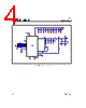
️· Fig. 1: Reference Design Schematic - Detailed electrical diagram of the circuit.
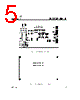
️· Fig. 3: Component Placement Top Layer - Shows the placement of components on the top layer of the PCB.
️· Fig. 3: Component Placement Bottom Layer - Shows the placement of components on the bottom layer of the PCB.
️· Fig. 6: Current Limit Adjustment using R_LIM - A diagram illustrating how to adjust the current limit.
️· Fig. 2: Typical Efficiency vs. Current - Shows the efficiency of the design over a range of currents.
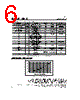
️· Table 2: Reference Design Bill of Materials – Complete list of parts.
Essentially, this document provides a comprehensive guide for engineers to design and implement a power solution based on the IRDCiP1001-B power block.
1. Project Overview:
️· Product: IRDCiP1001-B is a power block (likely a power management IC) from International Rectifier (now part of Infineon). It's designed for applications needing a compact and integrated power solution.
️· Reference Design: This document provides a complete reference design for utilizing the IRDCiP1001-B. This includes schematics, component placement diagrams, and a detailed bill of materials (BOM).
️· Purpose: The design aims to demonstrate how to implement the IRDCiP1001-B effectively in a real-world application.
2. Key Design Features & Components:
️· Operating Range: Designed for input voltages from 5V to 12V.
️· Bill of Materials (BOM): A complete list of components, including:
- Capacitors (C1-C16) – Various values, voltage ratings, and types (X5R, X7R, Tantalum).
- Schottky Diode (D1) – For rectification and protection.
- Inductor (L1 & L2) – L1 is specifically used, L2 is not populated.
- Resistors (R1-R7) – Various values for current limiting and voltage adjustment.
- DIP Switch (SW1) – For configuration/selection.
- Test Points (TP1-TP5) – For testing and debugging.
- Power Block (U1) – The core IRDCiP1001-B chip.
️· Adjustable Current Limit: The design allows adjustment of the current limit using a resistor (R_LIM) – see Figure 6.
️· Output Voltage Adjustment: Resistors R3 & R4 are used to adjust the output voltage. Equation 1 provides the formula for calculating the resistor values.
3. Supporting Documentation & Application Notes:
️· The design references several application notes (AN-1028, AN-1029, AN-1030) for guidance on:
- Assembly and rework considerations for BGA packages.
- PCB layout optimization for thermal and electrical performance.
- Validating operating conditions and thermal environment.
4. Important Disclaimers:
️· The design is provided as a reference and requires customer verification and testing.
️· International Rectifier (now Infineon) does not guarantee suitability for all applications and is not liable for damages resulting from its use.
5. Key Diagrams/Figures:
️· Fig. 1: Reference Design Schematic - Detailed electrical diagram of the circuit.
️· Fig. 3: Component Placement Top Layer - Shows the placement of components on the top layer of the PCB.
️· Fig. 3: Component Placement Bottom Layer - Shows the placement of components on the bottom layer of the PCB.
️· Fig. 6: Current Limit Adjustment using R_LIM - A diagram illustrating how to adjust the current limit.
️· Fig. 2: Typical Efficiency vs. Current - Shows the efficiency of the design over a range of currents.
️· Table 2: Reference Design Bill of Materials – Complete list of parts.
Essentially, this document provides a comprehensive guide for engineers to design and implement a power solution based on the IRDCiP1001-B power block.
| Part No. | IRDCIP1001-B |
| Manufacturer | IRF |
| Size | 586 Kbytes |
| Pages | 6 pages |
| Description | 200kHz to 300kHz, 20A, 5VIN to 12VIN Single Phase Synchronous Buck Converter using iP1001 |
| Does ALLDATASHEET help your business so far? [ DONATE ] |
About Alldatasheet | Advertisement | Contact us | Privacy Policy | Link to Datasheet | Link Exchange | Manufacturer List All Rights Reserved©Alldatasheet.com |
| Russian : Alldatasheetru.com | Korean : Alldatasheet.co.kr | Spanish : Alldatasheet.es | French : Alldatasheet.fr | Italian : Alldatasheetit.com Portuguese : Alldatasheetpt.com | Polish : Alldatasheet.pl | Vietnamese : Alldatasheet.vn Indian : Alldatasheet.in | Mexican : Alldatasheet.com.mx | British : Alldatasheet.co.uk | New Zealand : Alldatasheet.co.nz |
|
Family Site : ic2ic.com |
icmetro.com |
 New Zealand ▼
  English
 Chinese
 German
 Japanese
 Russian
 Korean
 Spanish
 French
 Italian
 Portuguese
 Polish
 Vietnamese
 Indian
 Mexican
 British