|
Electronic Components Datasheet Search |
|
|
Electronic Components Datasheet Search |
|
INMP521ACEZ-R0 Datasheet(PDF) 13 Page - TDK Electronics |
|
|
|||||||||||||||||||||||||||||
INMP521ACEZ-R0 Datasheet(HTML) 13 Page - TDK Electronics |
|
|
13 / 20 page 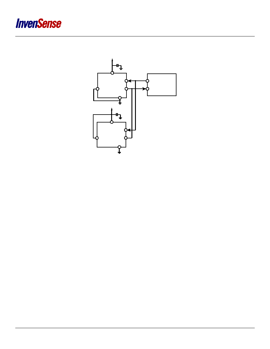 INMP521 Figure 12. Stereo PDM Microphone Connection to Codec Decouple the VDD pin of the INMP521 to GND with a 0.1 µF capacitor. Place this capacitor as close to VDD as the printed circuit board (PCB) layout allows. Do not use a pull-up or pull-down resistor on the PDM data signal line because the resistor can pull the signal to an incorrect state during the period that the signal line is tristated. CLOCK OUTPUT CODEC 0.1µF 1.8V TO 3.3V GND L/R SELECT DATA INMP521 CLK VDD DATA INPUT 0.1µF 1.8V TO 3.3V GND L/R SELECT DATA INMP521 CLK VDD Page 13 of 20 Document Number: DS-INMP521-00 Revision: 1.0. |
|
|
Link URL |
| Does ALLDATASHEET help your business so far? [ DONATE ] |
About Alldatasheet | Advertisement | Contact us | Privacy Policy | Link to Datasheet | Link Exchange | Manufacturer List All Rights Reserved©Alldatasheet.com |
| Russian : Alldatasheetru.com | Korean : Alldatasheet.co.kr | Spanish : Alldatasheet.es | French : Alldatasheet.fr | Italian : Alldatasheetit.com Portuguese : Alldatasheetpt.com | Polish : Alldatasheet.pl | Vietnamese : Alldatasheet.vn Indian : Alldatasheet.in | Mexican : Alldatasheet.com.mx | British : Alldatasheet.co.uk | New Zealand : Alldatasheet.co.nz |
|
Family Site : ic2ic.com |
icmetro.com |
 New Zealand ▼
 English
 Chinese
 German
 Japanese
 Russian
 Korean
 Spanish
 French
 Italian
 Portuguese
 Polish
 Vietnamese
 Indian
 Mexican
 British
 New Zealand