|
Electronic Components Datasheet Search |
|
|
Electronic Components Datasheet Search |
|
INMP441ACEZ-R0 Datasheet(PDF) 15 Page - List of Unclassifed Manufacturers |
|
|
|||||||||||||||||||||||||||||
INMP441ACEZ-R0 Datasheet(HTML) 15 Page - List of Unclassifed Manufacturers |
|
|
15 / 21 page 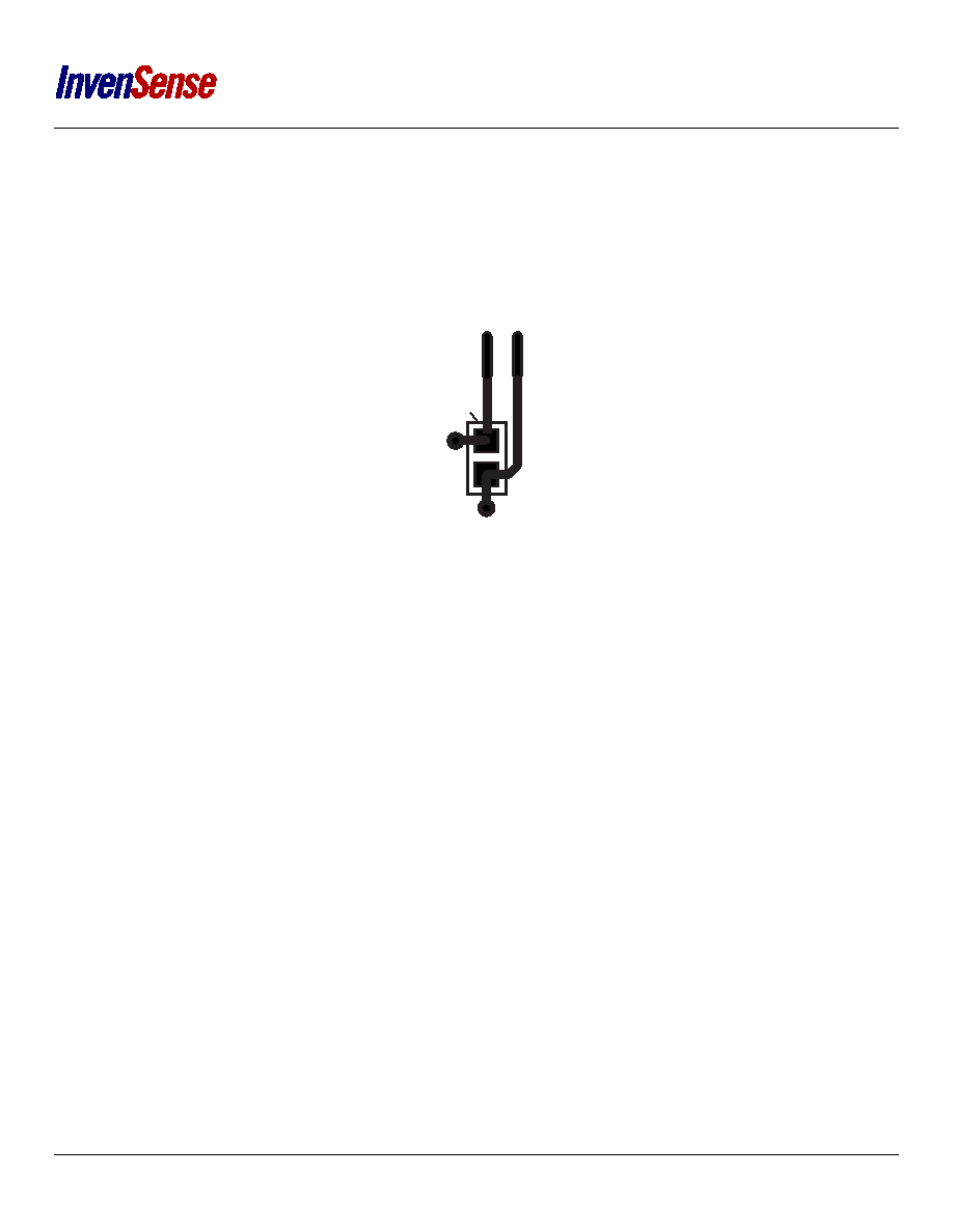 INMP441 APPLICATIONS INFORMATION POWER-SUPPLY DECOUPLING For best performance and to avoid potential parasitic artifacts, placing a 0.1 µF ceramic type X7R or better capacitor between Pin 7 (VDD) and ground is strongly recommended. The capacitor should be placed as close to Pin 7 as possible. The connections to each side of the capacitor should be as short as possible, and the trace should stay on a single layer with no vias. For maximum effectiveness, locate the capacitor equidistant from the power and ground pins, or if equidistant placement is not possible, slightly closer to the power pin. Thermal connections to the ground planes should be made on the far side of the capacitor, as shown in Figure 13. Figure 13. Recommended Power-Supply Bypass Capacitor Layout VDD GND TO GND TO VDD CAPACITOR Page 15 of 21 Document Number: DS-INMP441-00 Revision: 1.1 |
|
|
Link URL |
| Does ALLDATASHEET help your business so far? [ DONATE ] |
About Alldatasheet | Advertisement | Contact us | Privacy Policy | Link to Datasheet | Link Exchange | Manufacturer List All Rights Reserved©Alldatasheet.com |
| Russian : Alldatasheetru.com | Korean : Alldatasheet.co.kr | Spanish : Alldatasheet.es | French : Alldatasheet.fr | Italian : Alldatasheetit.com Portuguese : Alldatasheetpt.com | Polish : Alldatasheet.pl | Vietnamese : Alldatasheet.vn Indian : Alldatasheet.in | Mexican : Alldatasheet.com.mx | British : Alldatasheet.co.uk | New Zealand : Alldatasheet.co.nz |
|
Family Site : ic2ic.com |
icmetro.com |
 New Zealand ▼
 English
 Chinese
 German
 Japanese
 Russian
 Korean
 Spanish
 French
 Italian
 Portuguese
 Polish
 Vietnamese
 Indian
 Mexican
 British
 New Zealand