|
Electronic Components Datasheet Search |
|
|
Electronic Components Datasheet Search |
|
MXCB-V2-R3/Q Datasheet(PDF) 5 Page - M-System Co.,Ltd. |
|
|
|||||||||||||||||||||||||||||
MXCB-V2-R3/Q Datasheet(HTML) 5 Page - M-System Co.,Ltd. |
|
|
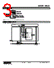
5 / 6 page 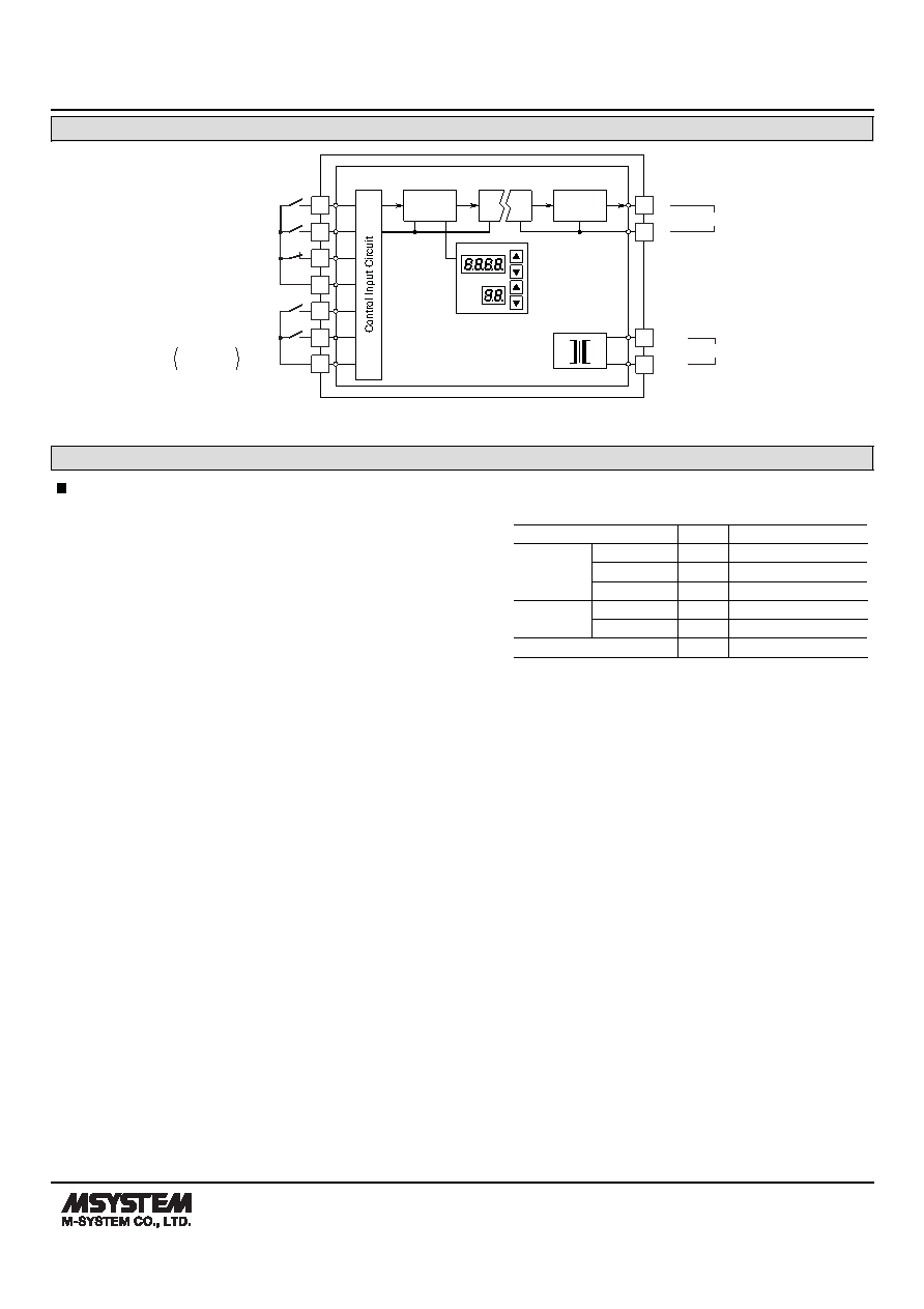 MODEL: MXCB MXCB SPECIFICATIONS ES-1745 Rev.8 Page 5/6 http://www.m-system.co.jp/ SCHEMATIC CIRCUITRY & CONNECTION DIAGRAM Isolation D/A Converter Digital Computation Base Socket DATA ITEM 5 3 4 10 11 UP 9 From SOFT-TERMINAL DOWN COM STOP From COMPUTER 6 UP DOWN COM Effective only in MAN mode 1 7 U(+) V(–) 8 POWER + – OUTPUT 2 FUNCTIONS COMMAND TERM. SIGNAL STATUS UP 3 – 6 1 0 0 1 – – – – Computer DOWN 4 – 6 0 1 0 1 – – – – STOP 5 – 6 1 1 1 1 0 0 0 0 ST/STL UP 9 – 11 – – – – 1 0 0 1 DOWN 10 – 11 – – – – 0 1 0 1 Output of the MXCB 1 – 2 ↑ ↓ H H ↑ ↓ H H [Keys] 1 : ON 0 : OFF – : ON or OFF H : Hold ↑ : Increase ↓ : Decrease • MXCB Used Independently In normal operating mode, the MXCB responds to UP/DOWN signals from the computer in the preset ramp rate. If the computer fails, this will be detected as a “STOP” command and output will be held at the value prior to the breakdown. You can increase the output signal by closing across the terminals 9 – 11, and decrease it by closing 10 – 11. The output responds in the preset ramp rate. • MXCB Used in Combination with ST/STL In normal operating mode, the MXCB responds to UP/DOWN signals from the computer in the preset ramp rate. If the computer fails, the “STOP” command will override computer output and put the unit in the manual operation mode by the ST/STL. Using the top-mounted UP or DOWN key, output can be increased or decreased in the preset ramp rate. Output signal value can be read on the top-mounted indicator. For more precise control, use the monitor terminals. Also the computer input can be overridden with the AUTO/MANUAL selector on the Soft-Terminal. This is useful when you need to change the output quickly during automatic operation by the computer control. DEFAULT SETTING |
|
|
Link URL |
| Does ALLDATASHEET help your business so far? [ DONATE ] |
About Alldatasheet | Advertisement | Contact us | Privacy Policy | Link to Datasheet | Link Exchange | Manufacturer List All Rights Reserved©Alldatasheet.com |
| Russian : Alldatasheetru.com | Korean : Alldatasheet.co.kr | Spanish : Alldatasheet.es | French : Alldatasheet.fr | Italian : Alldatasheetit.com Portuguese : Alldatasheetpt.com | Polish : Alldatasheet.pl | Vietnamese : Alldatasheet.vn Indian : Alldatasheet.in | Mexican : Alldatasheet.com.mx | British : Alldatasheet.co.uk | New Zealand : Alldatasheet.co.nz |
|
Family Site : ic2ic.com |
icmetro.com |
 New Zealand ▼
 English
 Chinese
 German
 Japanese
 Russian
 Korean
 Spanish
 French
 Italian
 Portuguese
 Polish
 Vietnamese
 Indian
 Mexican
 British
 New Zealand