|
Electronic Components Datasheet Search |
|
|
Electronic Components Datasheet Search |
|
R3-ND3-R Datasheet(PDF) 1 Page - M-System Co.,Ltd. |
|
|
|||||||||||||||||||||||||||||
R3-ND3-R Datasheet(HTML) 1 Page - M-System Co.,Ltd. |
|
|
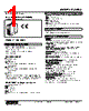
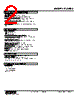
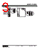
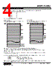
1 / 7 page 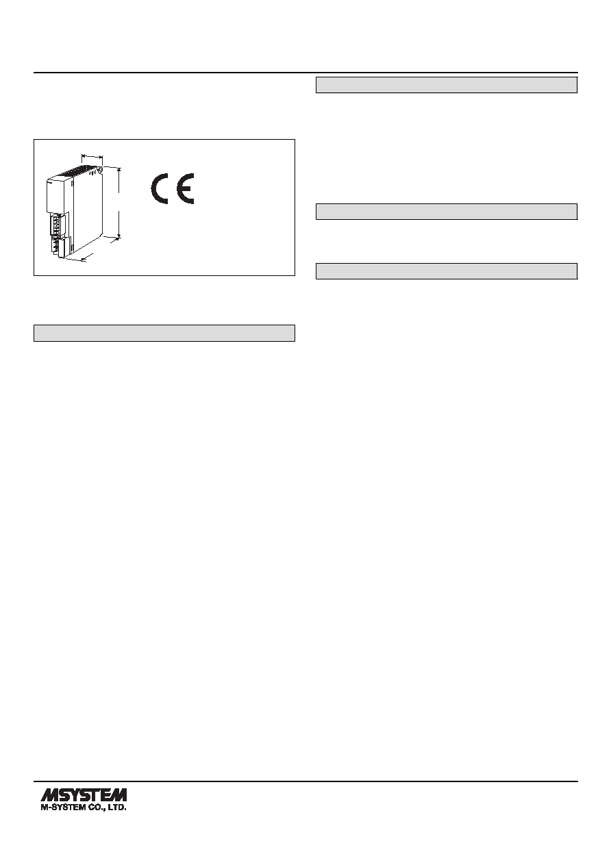 MODEL: R3-ND3 R3-ND3 SPECIFICATIONS ES-8382 Rev.17 Page 1/7 https://www.m-system.co.jp/ Remote I/O R3 Series DeviceNet INTERFACE MODULE (for 64-point analog signals) 109 [4.29] 27.5 [1.08] 130 [5.12] mm [inch] MODEL: R3-ND3-[1][2] ORDERING INFORMATION • Code number: R3-ND3-[1][2] Specify a code from below for each of [1] and [2]. (e.g. R3-ND3-R/CE/Q) • Specify the specification for option code /Q (e.g. /C01/SET) [1] POWER INPUT N: No power supply AC Power K3: 100 – 120 V AC (Operational voltage range 85 - 132 V, 47 - 66 Hz) * (CE not available) L3: 200 – 240 V AC (Operational voltage range 170 - 264 V, 47 - 66 Hz) * (CE not available) DC Power R: 24 V DC (Operational voltage range 24 V ±10 %, ripple 10 %p-p max.) * * Not selectable for use with independent power modules or network modules with the internal power input options. [2] OPTIONS (multiple selections) Standards & Approvals blank: Without CE /CE: CE marking Other Options blank: none /Q: Option other than the above (specify the specification) SPECIFICATIONS OF OPTION: Q (multiple selections) COATING (For the detail, refer to M-System's web site.) /C01: Silicone coating /C02: Polyurethane coating /C03: Rubber coating EX-FACTORY SETTING /SET: Preset according to the Ordering Information Sheet (No. ESU-8353) RELATED PRODUCTS • EDS file (downloadable at M-System’s web site.) GENERAL SPECIFICATIONS Connection DeviceNet: Euro type connector terminal (applicable wire size: 0.2 to 2.5 mm2, stripped length 7 mm) Internal bus: Via the Installation Base (model: R3-BSx) Internal power: Via the Installation Base (model: R3-BSx) Power input, RUN contact output: M3 separable screw terminal (torque 0.5 N·m) Screw terminal: Nickel-plated steel Isolation: DeviceNet to internal bus or internal power to power input to RUN contact output to FG Input error data setting: Input value setting at input module error with side DIP SW Dual communication setting: Set with the side DIP switch Data allocation setting: Set with the side DIP switch ■ RUN CONTACT OUTPUT RUN contact: Turns ON when both MS and NS LEDs are green (DeviceNet in normal communication). Rated load: 250 V AC @ 0.5 A (cos ø = 1) 30 V DC @ 0.5 A (resistive load) (Less than 50 V AC to conform with EU Directive) Maximum switching voltage: 250 V AC or 30 V DC Maximum switching power: 250 VA or 150 W Minimum load: 1 V DC @ 1 mA Mechanical life: 2 × 10⁷ cycles (300 cycles/min.) When driving an inductive load, external contact protection and noise quenching recommended. |
Similar Part No. - R3-ND3-R |
|
Similar Description - R3-ND3-R |
|
|
|
Link URL |
| Does ALLDATASHEET help your business so far? [ DONATE ] |
About Alldatasheet | Advertisement | Contact us | Privacy Policy | Link to Datasheet | Link Exchange | Manufacturer List All Rights Reserved©Alldatasheet.com |
| Russian : Alldatasheetru.com | Korean : Alldatasheet.co.kr | Spanish : Alldatasheet.es | French : Alldatasheet.fr | Italian : Alldatasheetit.com Portuguese : Alldatasheetpt.com | Polish : Alldatasheet.pl | Vietnamese : Alldatasheet.vn Indian : Alldatasheet.in | Mexican : Alldatasheet.com.mx | British : Alldatasheet.co.uk | New Zealand : Alldatasheet.co.nz |
|
Family Site : ic2ic.com |
icmetro.com |
 New Zealand ▼
 English
 Chinese
 German
 Japanese
 Russian
 Korean
 Spanish
 French
 Italian
 Portuguese
 Polish
 Vietnamese
 Indian
 Mexican
 British
 New Zealand