|
Electronic Components Datasheet Search |
|
|
Electronic Components Datasheet Search |
|
AOGW220-R Datasheet(PDF) 28 Page - IDEC Corporation |
|
|
|||||||||||||||||||||||||||||
AOGW220-R Datasheet(HTML) 28 Page - IDEC Corporation |
|
|
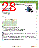
28 / 41 page 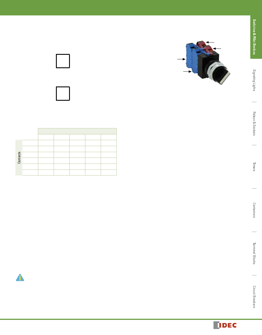 723 800-262-IDEC (4332) • USA & Canada ø22mm - TW Series Switches & Pilot Devices 1904032203 Custom Selector Switch Building Guide To build a custom selector switch, follow these steps. Step 1 How many positions of the switch are needed? # of positions (2, 3, 4, 5) Step 2 How many contacts should there be? # of isolated contacts (maximum 6) Step 3 Fill in the Truth Table (X = closed, 0 = open) Knob Position 1 2 3 4 5 1 2 3 4 5 6 Step 4 If building a 2 position selector, skip this step. (2 position selectors have only one cam) If building a 3, 4, or 5 position selector, determine appropriate cam as follows: • Look at Row 1 from above table and locate an identical row in the operator truth tables (See next page). • Repeat for all rows. The user must find one operator that contains all rows from above table. • Record the operator cam version. Step 5 Build by placing appropriate contact in appropriate mounting position for each desired row on operator cam truth table. “L” and “R” refer to mounting on left or right side of operator as viewed from the front of the panel. Step 6 Develop an assembly part number (if necessary) as follows: follow standard numbering nomenclature for selector switches (see pages 712 or 716. In place of the “Circuit Number” indicate the cam number and contact arrangement as such ASW322-3-OELCSS, where “3” is the cam number, and contact arrangement “OELCXX” calls out individual contact mounting locations in order (see diagram above). O=NO, C=NC, E=NO-EM, L=NC-LB, X= no contact. Part number must designate all 6 pos- sible mounting locations. Caution: Before putting any custom selector switch into use, the user should use an ohmmeter to test for desired performance. 1. For Operator Truth Tables, see next page. L Mounting Positions 3 4 1 2 R |
|
Link URL |
| Does ALLDATASHEET help your business so far? [ DONATE ] |
About Alldatasheet | Advertisement | Contact us | Privacy Policy | Link to Datasheet | Link Exchange | Manufacturer List All Rights Reserved©Alldatasheet.com |
| Russian : Alldatasheetru.com | Korean : Alldatasheet.co.kr | Spanish : Alldatasheet.es | French : Alldatasheet.fr | Italian : Alldatasheetit.com Portuguese : Alldatasheetpt.com | Polish : Alldatasheet.pl | Vietnamese : Alldatasheet.vn Indian : Alldatasheet.in | Mexican : Alldatasheet.com.mx | British : Alldatasheet.co.uk | New Zealand : Alldatasheet.co.nz |
|
Family Site : ic2ic.com |
icmetro.com |
 New Zealand ▼
 English
 Chinese
 German
 Japanese
 Russian
 Korean
 Spanish
 French
 Italian
 Portuguese
 Polish
 Vietnamese
 Indian
 Mexican
 British
 New Zealand