|
Electronic Components Datasheet Search |
|
|
Electronic Components Datasheet Search |
|
20VLP10-R Datasheet(PDF) 3 Page - Vishay Siliconix |
|
|
|||||||||||||||||||||||||||||
20VLP10-R Datasheet(HTML) 3 Page - Vishay Siliconix |
|
|
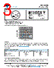
3 / 5 page 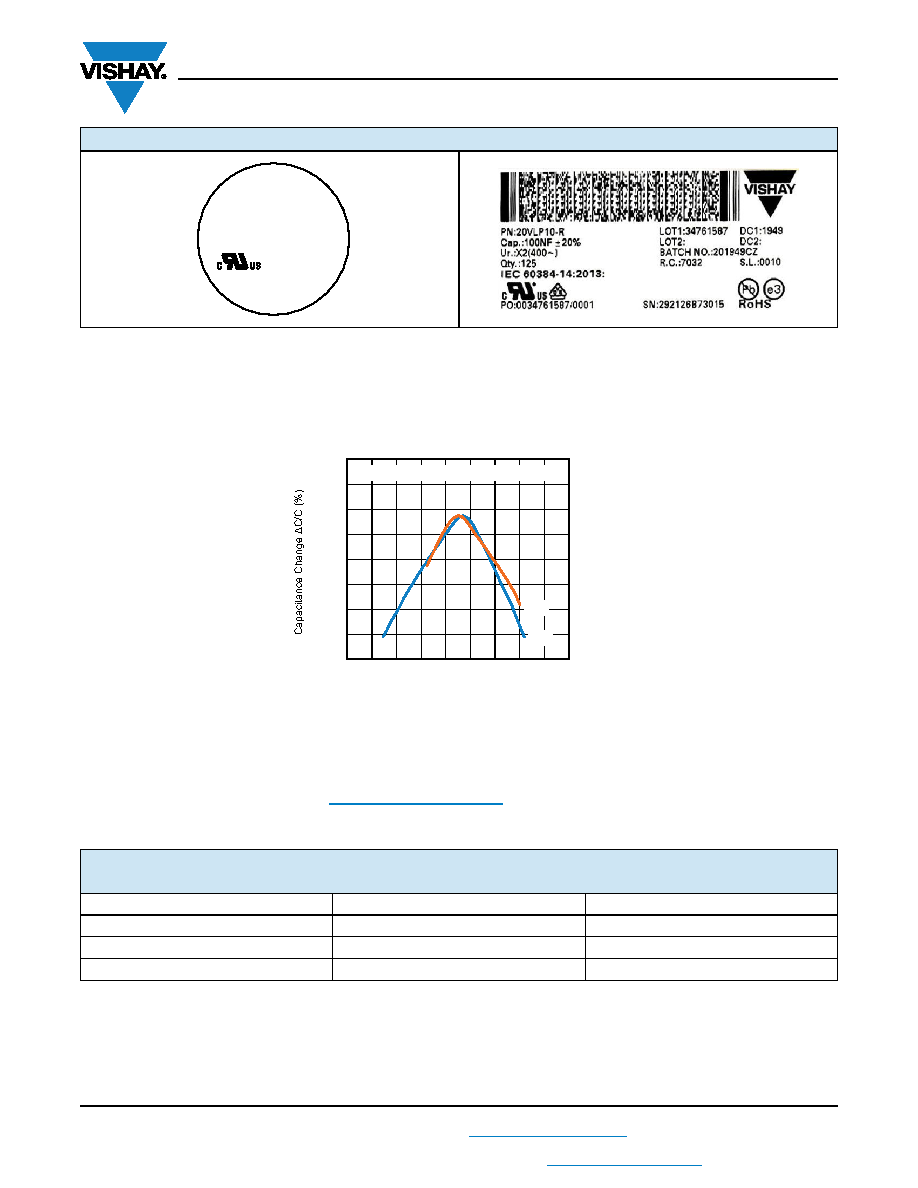 20VL Series www.vishay.com Vishay Cera-Mite Revision: 23-Jul-2021 3 Document Number: 23107 For technical questions, contact: ceramitesupport@vishay.com THIS DOCUMENT IS SUBJECT TO CHANGE WITHOUT NOTICE. THE PRODUCTS DESCRIBED HEREIN AND THIS DOCUMENT ARE SUBJECT TO SPECIFIC DISCLAIMERS, SET FORTH AT www.vishay.com/doc?91000 Notes • Marking IEC 60384-14 does not apply for Ø 9 mm • “XX - XXX” is a placeholder for date code and lot number: “XX -” is the year and month according to IEC 60062 “- XXX” is the last 3 digits of the lot number CAPACITANCE CHANGE VS. TEMPERATURE (Typical) STORAGE The capacitors must not be stored in a corrosive atmosphere, where sulphide or chloride gas, acid, alkali or salt are present. Exposure of the components to moisture, should be avoided. The solderability of the leads is not affected by storage of up to 24 months (temperature +10 °C to +40 °C, relative humidity up to 60 % RH). Class 2 ceramic dielectric capacitors are also subject to aging see general information (www.vishay.com/doc?23140). SOLDERING SOLDERING RECOMMENDATIONS Ceramic capacitors are very sensitive to rapid changes in temperature (thermal shock) therefore the solder heat resistance specification (see table above) should not be exceeded. Exposing the capacitor to excessive heating may result in thermal shocks that can crack the ceramic body. Similarly, excessive heating can cause the internal solder junction to melt. MARKING SOLDERING SPECIFICATIONS Soldering test for capacitors with wire leads: (according to IEC 60068-2-20, solder bath method) SOLDERABILITY RESISTANCE TO SOLDERING HEAT Soldering temperature (235 ± 5) °C (260 ± 5) °C Soldering duration (2 ± 0.5) s (10 ± 1) s Distance from component body 2 mm 5 mm IEC 60384-14 20VL 203M CM XX - XXX Sample X2 400V~ 10 100 1000 10000 -100 -80 -60 -40 -20 0 20 40 60 -55 -35 -15 5 25 45 65 85 105 125 Axis Title Temperature (°C) Z5U Y5V Temperature dependence of the capacitance |
|
|
Link URL |
| Does ALLDATASHEET help your business so far? [ DONATE ] |
About Alldatasheet | Advertisement | Contact us | Privacy Policy | Link to Datasheet | Link Exchange | Manufacturer List All Rights Reserved©Alldatasheet.com |
| Russian : Alldatasheetru.com | Korean : Alldatasheet.co.kr | Spanish : Alldatasheet.es | French : Alldatasheet.fr | Italian : Alldatasheetit.com Portuguese : Alldatasheetpt.com | Polish : Alldatasheet.pl | Vietnamese : Alldatasheet.vn Indian : Alldatasheet.in | Mexican : Alldatasheet.com.mx | British : Alldatasheet.co.uk | New Zealand : Alldatasheet.co.nz |
|
Family Site : ic2ic.com |
icmetro.com |
 New Zealand ▼
 English
 Chinese
 German
 Japanese
 Russian
 Korean
 Spanish
 French
 Italian
 Portuguese
 Polish
 Vietnamese
 Indian
 Mexican
 British
 New Zealand