|
Electronic Components Datasheet Search |
|
|
Electronic Components Datasheet Search |
|
AD8189ARUZ-R7 Datasheet(PDF) 21 Page - Analog Devices |
|
|
|||||||||||||||||||||||||||||
AD8189ARUZ-R7 Datasheet(HTML) 21 Page - Analog Devices |
|
|
21 / 24 page 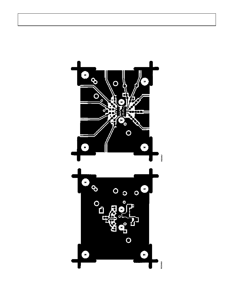 AD8188/AD8189 Rev. 0 | Page 21 of 24 EVALUATION BOARD An evaluation board has been designed and is offered for running the AD8188/AD8189 on a single supply. The inputs and outputs are ac-coupled and terminated with 75 Ω resistors. For the AD8189, a potentiometer is provided to allow setting VREF at any value between VCC and ground. The logic control signals can be statically set by adding or removing a jumper. If a fast signal is required to drive the logic pins, an SMA connector can be used to deliver the signal, and a place for a termination resistor is provided. Figure 57. Component Side Board Layout Figure 58. Circuit Side Board Layout |
|
|
Link URL |
| Does ALLDATASHEET help your business so far? [ DONATE ] |
About Alldatasheet | Advertisement | Contact us | Privacy Policy | Link to Datasheet | Link Exchange | Manufacturer List All Rights Reserved©Alldatasheet.com |
| Russian : Alldatasheetru.com | Korean : Alldatasheet.co.kr | Spanish : Alldatasheet.es | French : Alldatasheet.fr | Italian : Alldatasheetit.com Portuguese : Alldatasheetpt.com | Polish : Alldatasheet.pl | Vietnamese : Alldatasheet.vn Indian : Alldatasheet.in | Mexican : Alldatasheet.com.mx | British : Alldatasheet.co.uk | New Zealand : Alldatasheet.co.nz |
|
Family Site : ic2ic.com |
icmetro.com |
 New Zealand ▼
 English
 Chinese
 German
 Japanese
 Russian
 Korean
 Spanish
 French
 Italian
 Portuguese
 Polish
 Vietnamese
 Indian
 Mexican
 British
 New Zealand