 |
Electronic Components Datasheet Search |
|
|
Electronic Components Datasheet Search |
|
PL66X-XXQCL-R Datasheet(PDF) 13 Page - PhaseLink Corporation |
|
|
|||||||||||||||||||||||||||||
PL66X-XXQCL-R Datasheet(HTML) 13 Page - PhaseLink Corporation |
|
|
13 / 15 page 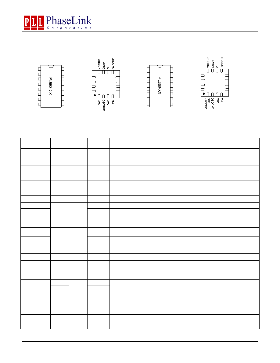 Analog Frequency Multiplier PL660 and PL663 XO Families 47745 Fremont Blvd., Fremont, California 94538 TEL (510) 492-0990, FAX (510) 492-0991 www.phaselink.com Rev. 3/20/07 Page 13 PACKAGE PIN DESCRIPTION AND ASSIGNMENT 1 2 3 4 5 6 7 8 9 10 11 12 13 14 15 GNDOSC XIN XOUT OE L4X VDDOSC L2X VDDOSC OESEL VDDANA VDDBUF QBAR Q OSCOFFSEL 16 1 2 3 4 5 6 7 8 9 10 11 12 13 14 15 GNDOSC XIN XOUT OE DNC GNDANA L2X VDDOSC VDDANA OESEL VDDBUF QBAR Q GNDBUF 16 OE XOUT 1 2 3 4 8 7 6 5 1 2 1 1 1 0 9 1 3 1 4 1 5 1 6 GNDANA DNC OESEL L2X VDDOSC VDDANA OE XOUT VDDOSC L4X VDDANA L2X VDDOSC OESEL 1 2 3 4 8 7 6 5 1 2 1 1 1 0 9 1 3 1 4 1 5 1 6 GNDBUF DNC DNC DNC PL660-XX PL663-XX 2x AFM Package Pin Out 4x AFM Package Pin Out PIN ASSIGNMENTS Name Pin # Type Product Description DNC 2X Do Not Connect. OSCOFFSEL 1 I 4X Set to “0” (GND) to turn off the oscillator when outputs are disabled (OE). Default (no connect) is OSC always on. GNDOSC 2 P 2X & 4X GND connection for oscillator. DNC 3 I 2X & 4X Do Not Connect. XIN 4 I 2X & 4X Input from crystal oscillator circuitry. XOUT 5 O 2X & 4X Output from crystal oscillator circuitry. OE 6 I 2X & 4X Output Enable input. See “OE LOGIC SELECTION TABLE”. DNC 2X Do Not Connect. L4X 7 I 4X External inductor connection. The inductor is recommended to be a high Q small size 0402 or 0603 SMD component, and must be placed between L4X and adjacent VDDOSC. Place inductor as close to the IC as possible to minimize parasitic effects and to maintain inductor Q. This inductor is used with 4x AFMs. GNDANA 2X GND connection. VDDOSC 8 P 4X VDD connection for oscillator circuitry. VDDOSC should be separately decoupled from other VDDs whenever possible. GNDBUF 9 P 2X & 4X GND connection. Q 10 O 2X & 4X PECL/LVDS/CMOS output. QBAR 11 O 2X & 4X Complementary PECL/LVDS output or in-phase CMOS. VDDBUF 12 P 2X & 4X VDD connection for output buffer circuitry. VDDBUF should be separately decoupled from other VDDs whenever possible. 13 2X OESEL 14 I 4X Selector input to choose the OE control logic (see “OE SELECTION TABLE”). If no connection is applied, value will be set to default through internal pull-down resistor. 14 2X VDDANA 13 P 4X VDD connection for analog circuitry.VDDANA should be separately decoupled from other VDDs whenever possible. VDDOSC 15 P 2X & 4X VDD connection for oscillator. VDD should be separately decoupled from other VDDs whenever possible. L2X 16 I 2X & 4X External inductor connection. The inductor is recommended to be a high Q small size 0402 or 0603 SMD component, and must be placed between L2X and adjacent VDDOSC. Place inductor as close to the IC as possible to minimize parasitic effects and to maintain inductor Q. Note: 663-xx devices are 2x multipliers, and 660-xx devices are 4x multipliers. |
|
|
Link URL |
| Does ALLDATASHEET help your business so far? [ DONATE ] |
About Alldatasheet | Advertisement | Contact us | Privacy Policy | Link to Datasheet | Link Exchange | Manufacturer List All Rights Reserved©Alldatasheet.com |
| Russian : Alldatasheetru.com | Korean : Alldatasheet.co.kr | Spanish : Alldatasheet.es | French : Alldatasheet.fr | Italian : Alldatasheetit.com Portuguese : Alldatasheetpt.com | Polish : Alldatasheet.pl | Vietnamese : Alldatasheet.vn Indian : Alldatasheet.in | Mexican : Alldatasheet.com.mx | British : Alldatasheet.co.uk | New Zealand : Alldatasheet.co.nz |
|
Family Site : ic2ic.com |
icmetro.com |
 New Zealand ▼
 English
 Chinese
 German
 Japanese
 Russian
 Korean
 Spanish
 French
 Italian
 Portuguese
 Polish
 Vietnamese
 Indian
 Mexican
 British
 New Zealand


