 |
Electronic Components Datasheet Search |
|
|
Electronic Components Datasheet Search |
|
STPM01FTR Datasheet(PDF) 21 Page - STMicroelectronics |
|
|
|||||||||||||||||||||||||||||
STPM01FTR Datasheet(HTML) 21 Page - STMicroelectronics |
|
|
21 / 56 page 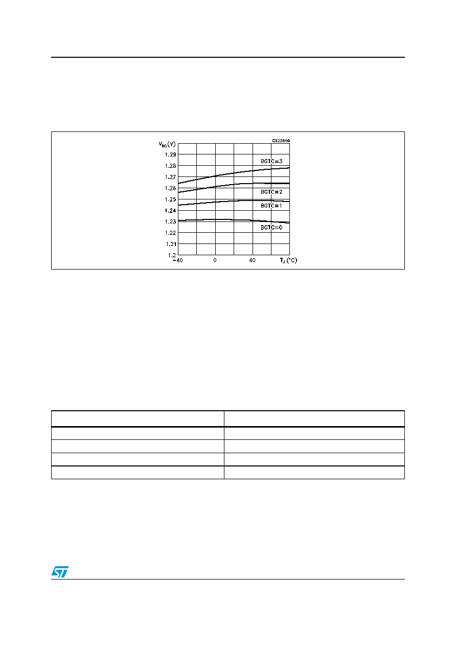 STPM01 Theory of operation 21/56 A BandGap voltage reference (VBG) of 1.23V ±1% is used as reference voltage level source for the two linear regulators and for the A/D converters. Also, this module produces several bias currents and voltages for all other analog modules and for the OTP module. The bandgap voltage can be compensated regardless to the temperature variations with the BGTC bits.. 8.8 Load monitoring The STPM01 includes a no load condition detection circuit with adjustable threshold. This circuit monitors the voltage and the current channels and, when the measured voltage is below the set threshold, the internal signal BIL becomes high. The information about this signal is also available in the status bit BIL. The no load condition occurs when the product between VRMS and IRMS register values is below a given value. This value can be set with the LTCH configuration bits. Four different no-load threshold values can be chosen according to the two configuration bits LTCH (see table 11). When a no load condition occurs (BIL=1) the integration of power is suspended and the tamper module is disabled. In standalone mode, if a no load condition is detected, the BIL signal blocks generation of pulses for stepper and forces SCLNLC pin to be low. If APL=2 (see 8.14) the LED pin continues providing the high frequency pulses, while if APL=3, the pulses are stopped as happens for MOP and MON. In peripheral mode, the BIL signal can be accessed only through the SPI interface. Figure 17. Bandgap temperature variation Table 11. No load detection thresholds LTCH KLTCH 0800 11600 23200 36400 |
|
Link URL |
| Does ALLDATASHEET help your business so far? [ DONATE ] |
About Alldatasheet | Advertisement | Contact us | Privacy Policy | Link to Datasheet | Link Exchange | Manufacturer List All Rights Reserved©Alldatasheet.com |
| Russian : Alldatasheetru.com | Korean : Alldatasheet.co.kr | Spanish : Alldatasheet.es | French : Alldatasheet.fr | Italian : Alldatasheetit.com Portuguese : Alldatasheetpt.com | Polish : Alldatasheet.pl | Vietnamese : Alldatasheet.vn Indian : Alldatasheet.in | Mexican : Alldatasheet.com.mx | British : Alldatasheet.co.uk | New Zealand : Alldatasheet.co.nz |
|
Family Site : ic2ic.com |
icmetro.com |
 New Zealand ▼
 English
 Chinese
 German
 Japanese
 Russian
 Korean
 Spanish
 French
 Italian
 Portuguese
 Polish
 Vietnamese
 Indian
 Mexican
 British
 New Zealand


