|
Electronic Components Datasheet Search |
|
|
Electronic Components Datasheet Search |
|
AD8422ACPZ-R7 Datasheet(PDF) 22 Page - Analog Devices |
|
|
|||||||||||||||||||||||||||||
AD8422ACPZ-R7 Datasheet(HTML) 22 Page - Analog Devices |
|
|
22 / 28 page 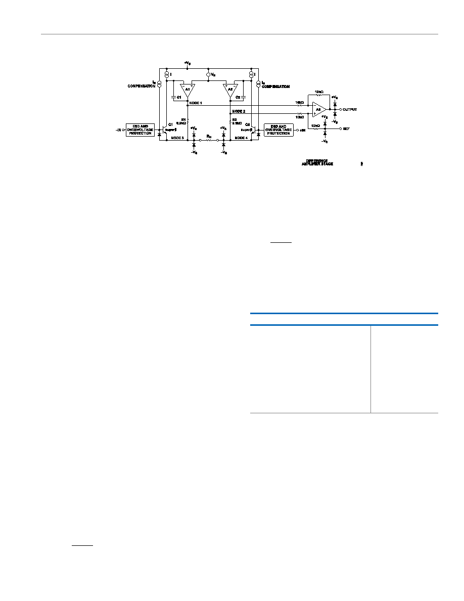 Data Sheet AD8422 THEORY OF OPERATION analog.com Rev. C | 22 of 28 Figure 56. Simplified Schematic ARCHITECTURE The AD8422 is based on the classic 3-op-amp instrumentation amplifier topology. This topology has two stages: a preamplifier to provide differential amplification followed by a difference amplifier that removes the common-mode voltage. Figure 56 shows a simpli- fied schematic of the AD8422. Topologically, Q1, A1, R1 and Q2, A2, R2 can be viewed as precision current feedback amplifiers that maintain a fixed current in the emitters of Q1 and Q2. Any change in the input signal forces the output voltages of A1 and A2 to change accordingly and maintain the Q1 and Q2 current at the correct value. This causes a precise diode drop from –IN and +IN to Node 3 and Node 4, respectively, so that the differential signal applied to the inputs is replicated across the RG pins. Any current through RG must also flow through R1 and R2, creating the gained differential voltage between Node 1 and Node 2. The amplified differential signal and the common-mode signal are applied to a difference amplifier that rejects the common-mode voltage but preserves the amplified differential voltage. Laser-trimmed resistors allow for a highly accurate in-amp with a gain error of less than 0.01% and a CMRR that exceeds 94 dB (G = 1). The supply current is precisely trimmed to reduce uncertainties due to part-to-part variations in power dissipation and noise. The high performance pinout and special attention to design and layout allow for high CMRR across a wide frequency and temperature range. Using superbeta input transistors and bias current compen- sation, the AD8422 offers extremely high input impedance and low bias current, as well as very low voltage noise while using only 300 µA supply current. The overvoltage protection scheme allows the input to go 40 V from the opposite rail at all gains without compromising the noise performance. The transfer function of the AD8422 is VOUT = G × (VIN+ − VIN−) + VREF (1) where: G=1+19.8kΩRG (2) GAIN SELECTION Placing a resistor across the RG terminals sets the gain of the AD8422 that can be calculated by referring to Table 8 or by using the following gain equation: RG=19.8kΩG−1 (3) The AD8422 defaults to G = 1 when no gain resistor is used. Add the tolerance and gain drift of the RG resistor to the specifications of the AD8422 to determine the total gain accuracy of the system. When the gain resistor is not used, gain error and gain drift are minimal. Table 8. Gains Achieved Using 1% Resistors 1% Standard Table Value of RG (Ω) Calculated Gain 19.6 k 2.010 4.99 k 4.968 2.21 k 9.959 1.05 k 19.86 402 50.25 200 100.0 100 199.0 39.2 506.1 20 991.0 RG Power Dissipation The AD8422 duplicates the differential voltage across its inputs onto the RG resistor. Choose an RG resistor size that is sufficient to handle the expected power dissipation at ambient temperature. REFERENCE TERMINAL The output voltage of the AD8422 is developed with respect to the potential on the reference terminal. This can be used to apply a precise offset to the output signal. For example, a voltage source can be tied to the REF pin to level shift the output, allowing the AD8422 to drive a unipolar analog-to-digital converter (ADC). The REF pin is protected with ESD diodes and must not exceed either +VS or −VS by more than 0.3 V. |
|
Link URL |
| Does ALLDATASHEET help your business so far? [ DONATE ] |
About Alldatasheet | Advertisement | Contact us | Privacy Policy | Link to Datasheet | Link Exchange | Manufacturer List All Rights Reserved©Alldatasheet.com |
| Russian : Alldatasheetru.com | Korean : Alldatasheet.co.kr | Spanish : Alldatasheet.es | French : Alldatasheet.fr | Italian : Alldatasheetit.com Portuguese : Alldatasheetpt.com | Polish : Alldatasheet.pl | Vietnamese : Alldatasheet.vn Indian : Alldatasheet.in | Mexican : Alldatasheet.com.mx | British : Alldatasheet.co.uk | New Zealand : Alldatasheet.co.nz |
|
Family Site : ic2ic.com |
icmetro.com |
 New Zealand ▼
 English
 Chinese
 German
 Japanese
 Russian
 Korean
 Spanish
 French
 Italian
 Portuguese
 Polish
 Vietnamese
 Indian
 Mexican
 British
 New Zealand