 |
Electronic Components Datasheet Search |
|
|
Electronic Components Datasheet Search |
|
STPCELITE Datasheet(PDF) 76 Page - STMicroelectronics |
|
|
|||||||||||||||||||||||||||||
STPCELITE Datasheet(HTML) 76 Page - STMicroelectronics |
|
|
76 / 87 page 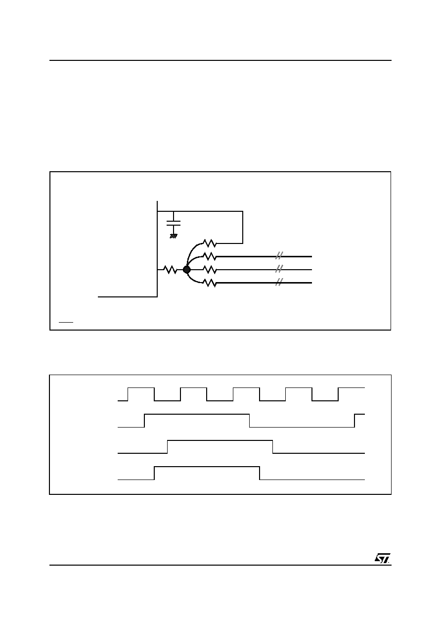 DESIGN GUIDELINES 76/87 Release 1.3 - January 29, 2002 This is preliminary information on a new product now in development or undergoing evaluation. Details are subject to change without notice. 6.4.3.3. Board Layout Issues The physical layout of the motherboard PCB assumed in this presentation is as shown in Figure 6-22. For the PCI interface, the most critical signal is the clock. Any skew between the clocks at the PCI components and the STPC will impact the timing budget. In order to get well matched clocks at all components it is recommended that all the PCI clocks are individually driven from a serial resistance with matched routing lengths. In other words, all clock line lengths that go from the resistor to the PCI chips (PCICLKx) must be identical. The figure below is for PCI devices soldered on- board. In the case of a PCI slot, the wire length must be shortened by 2.5" to compensate the clock layout on the PCI board. The maximum clock skew between all devices is 2ns according to PCI specifications. The Figure 6-23 describes a typical clock delay implementation. The exact timing constraints are listed in the PCI section of the Electrical Specifications Chapter. Figure 6-22. Typical PCI clock routing Length(PCICLKI) = Length(PCICLKx) with x = {A,B,C} Note: The value of 22 Ohms corresponds to tracks with Z0 = 70 Ohms. PCICLKI PCICLKO PCICLKA PCICLKB PCICLKC Device A Device B Device C Figure 6-23. Clocks relationships PCICLKO PCICLKI HCLK PCICLKx |
|
Link URL |
| Does ALLDATASHEET help your business so far? [ DONATE ] |
About Alldatasheet | Advertisement | Contact us | Privacy Policy | Link to Datasheet | Link Exchange | Manufacturer List All Rights Reserved©Alldatasheet.com |
| Russian : Alldatasheetru.com | Korean : Alldatasheet.co.kr | Spanish : Alldatasheet.es | French : Alldatasheet.fr | Italian : Alldatasheetit.com Portuguese : Alldatasheetpt.com | Polish : Alldatasheet.pl | Vietnamese : Alldatasheet.vn Indian : Alldatasheet.in | Mexican : Alldatasheet.com.mx | British : Alldatasheet.co.uk | New Zealand : Alldatasheet.co.nz |
|
Family Site : ic2ic.com |
icmetro.com |
 New Zealand ▼
 English
 Chinese
 German
 Japanese
 Russian
 Korean
 Spanish
 French
 Italian
 Portuguese
 Polish
 Vietnamese
 Indian
 Mexican
 British
 New Zealand


