 |
Electronic Components Datasheet Search |
|
|
Electronic Components Datasheet Search |
|
H8S2245 Datasheet(PDF) 607 Page - Renesas Technology Corp |
|
|
|||||||||||||||||||||||||||||
H8S2245 Datasheet(HTML) 607 Page - Renesas Technology Corp |
|
|
607 / 818 page 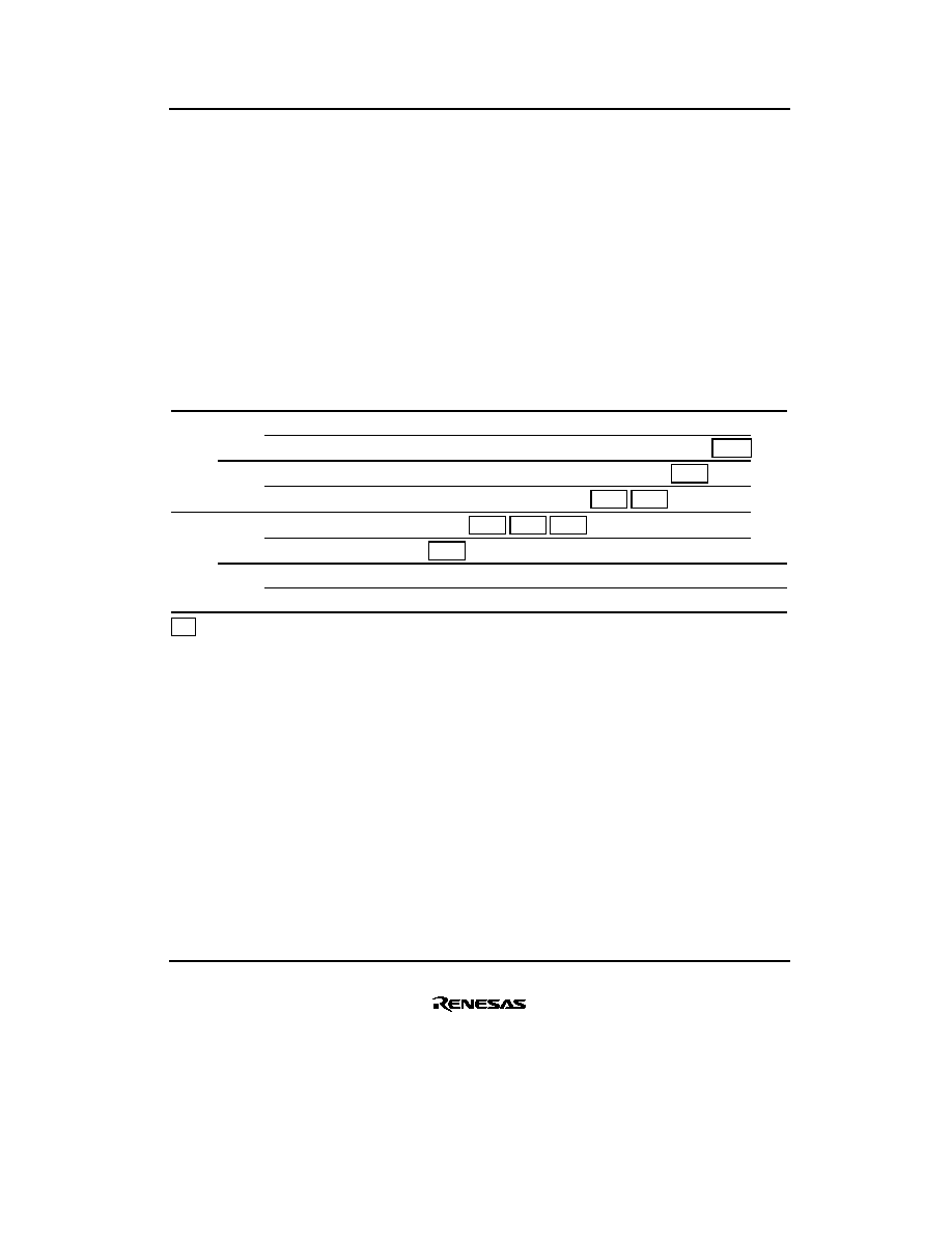 Section 18 Power-Down Modes Rev.3.00 Mar. 26, 2007 Page 565 of 772 REJ09B0355-0300 18.6.3 Setting Oscillation Stabilization Time after Clearing Software Standby Mode Bits STS2 to STS0 in SBYCR should be set as described below. Using a Crystal Oscillator Set bits STS2 to STS0 so that the standby time is at least 8 ms (the oscillation stabilization time). Table 18.4 shows the standby times for different operating frequencies and settings of bits STS2 to STS0. Table 18.4 Oscillation Stabilization Time Settings STS2 STS1 STS0 Standby Time 20 MHz 16 MHz 12 MHz 10 MHz 8 MHz 6 MHz 4 MHz 2 MHz Unit 0 0 0 8192 states 0.41 0.51 0.68 0.82 1.0 1.4 2.0 4.1 ms 1 16384 states 0.82 1.0 1.4 1.6 2.0 2.7 4.1 8.2 1 0 32768 states 1.6 2.0 2.7 3.3 4.1 5.5 8.2 16.4 1 65536 states 3.3 4.1 5.5 6.6 8.2 10.9 16.4 32.8 1 0 0 131072 states 6.6 8.2 10.9 13.1 16.4 21.8 32.8 65.5 1 262144 states 13.1 16.4 21.8 26.2 32.8 43.7 65.5 131.1 1 0 Reserved ——— ——— —— — 1 16 states 0.8 1.0 1.3 1.6 2.0 2.7 4.0 8.0 µs : Recommended time setting Using an External Clock Any value can be set. Normally, use of the minimum time is recommended. 18.6.4 Software Standby Mode Application Example Figure 18.2 shows an example in which a transition is made to software standby mode at the falling edge on the NMI pin, and software standby mode is cleared at the rising edge on the NMI pin. In this example, an NMI interrupt is accepted with the NMIEG bit in SYSCR cleared to 0 (falling edge specification), then the NMIEG bit is set to 1 (rising edge specification), the SSBY bit is set to 1, and a SLEEP instruction is executed, causing a transition to software standby mode. |
|
Link URL |
| Does ALLDATASHEET help your business so far? [ DONATE ] |
About Alldatasheet | Advertisement | Contact us | Privacy Policy | Link to Datasheet | Link Exchange | Manufacturer List All Rights Reserved©Alldatasheet.com |
| Russian : Alldatasheetru.com | Korean : Alldatasheet.co.kr | Spanish : Alldatasheet.es | French : Alldatasheet.fr | Italian : Alldatasheetit.com Portuguese : Alldatasheetpt.com | Polish : Alldatasheet.pl | Vietnamese : Alldatasheet.vn Indian : Alldatasheet.in | Mexican : Alldatasheet.com.mx | British : Alldatasheet.co.uk | New Zealand : Alldatasheet.co.nz |
|
Family Site : ic2ic.com |
icmetro.com |
 New Zealand ▼
 English
 Chinese
 German
 Japanese
 Russian
 Korean
 Spanish
 French
 Italian
 Portuguese
 Polish
 Vietnamese
 Indian
 Mexican
 British
 New Zealand


