|
Electronic Components Datasheet Search |
|
|
Electronic Components Datasheet Search |
|
OT391 Datasheet(PDF) 1 Page - Suntac Electronic Corp. |
|
|
|||||||||||||||||||||||||||||
OT391 Datasheet(HTML) 1 Page - Suntac Electronic Corp. |
|
|
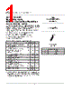
1 / 4 page 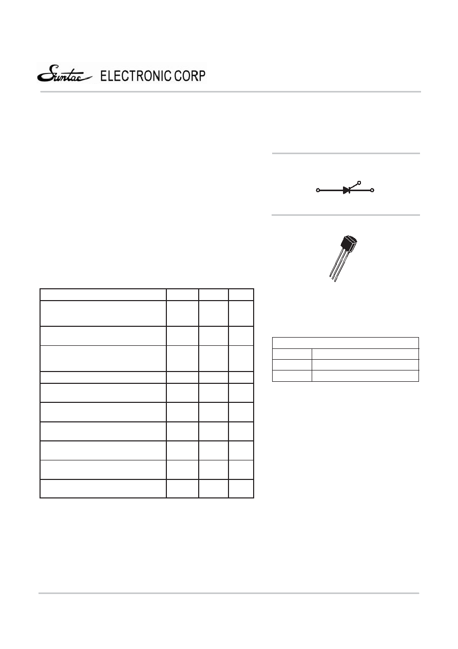 © Semiconductor Components Industries, LLC, 2000 December, 2000 – Rev. 0 1 Publication Order Number: NCR169D/D NCR169D Advance Information General Purpose Sensitive Gate Silicon Controlled Rectifier Reverse Blocking Thyristor PNPN device designed for line-powered general purpose applications such as relay and lamp drivers, small motor controls, gate drivers for larger thyristors, and sensing and detection circuits. Supplied in a cost effective plastic TO-92 package. • Sensitive Gate Allows Direct Triggering by Microcontrollers and Other Logic Circuits • On–State Current Rating of 0.8 Amperes RMS at 80°C • Surge Current Capability – 10 Amperes • Immunity to dV/dt – 20 V/µsec Minimum at 110°C • Glass-Passivated Surface for Reliability and Uniformity • Blocking Voltage to 600 Volts MAXIMUM RATINGS (TJ = 25°C unless otherwise noted) Rating Symbol Value Unit Peak Repetitive Off–State Voltage (Note 1.) (TJ = *40 to 110°C, Sine Wave, 50 to 60 Hz; Gate Open) VDRM, VRRM 600 Volts On-State RMS Current (TC = 80°C) 180° Conduction Angles IT(RMS) 0.8 Amp Peak Non-Repetitive Surge Current (1/2 Cycle, Sine Wave, 60 Hz, TJ = 25°C) ITSM 10 Amps Circuit Fusing Consideration (t = 10 ms) I2t 0.415 A2s Forward Peak Gate Power (TA = 25°C, Pulse Width v 1.0 µs) PGM 0.1 Watt Forward Average Gate Power (TA = 25°C, t = 20 ms) PG(AV) 0. 10 Watt Forward Peak Gate Current (TA = 25°C, Pulse Width v 1.0 µs) IGM 1. 0 Amp Reverse Peak Gate Voltage (TA = 25°C, Pulse Width v 1.0 µs) VGRM 5.0 Volts Operating Junction Temperature Range @ Rate VRRM and VDRM TJ –40 to 110 °C Storage Temperature Range Tstg –40 to 150 °C SCR 0.8 AMPERES RMS 600 VOLTS 4 (1) VDRM and VRRM for all types can be applied on a continuous basis. Ratings apply for zero or negative gate voltage; however, positive gate voltage shall not be applied concurrent with negative potential on the anode. Blocking voltages shall not be tested with a constant source such that the voltage ratings of the devices are exceeded. A STC OT391 TO−92 (TO−226) CASE 029 STYLE 10 3 2 1 PIN ASSIGNMENT 1 2 3 Gate Anode Cathode K G A |
Similar Part No. - OT391 |
|
Similar Description - OT391 |
|
|
|
Link URL |
| Does ALLDATASHEET help your business so far? [ DONATE ] |
About Alldatasheet | Advertisement | Contact us | Privacy Policy | Link to Datasheet | Link Exchange | Manufacturer List All Rights Reserved©Alldatasheet.com |
| Russian : Alldatasheetru.com | Korean : Alldatasheet.co.kr | Spanish : Alldatasheet.es | French : Alldatasheet.fr | Italian : Alldatasheetit.com Portuguese : Alldatasheetpt.com | Polish : Alldatasheet.pl | Vietnamese : Alldatasheet.vn Indian : Alldatasheet.in | Mexican : Alldatasheet.com.mx | British : Alldatasheet.co.uk | New Zealand : Alldatasheet.co.nz |
|
Family Site : ic2ic.com |
icmetro.com |
 New Zealand ▼
 English
 Chinese
 German
 Japanese
 Russian
 Korean
 Spanish
 French
 Italian
 Portuguese
 Polish
 Vietnamese
 Indian
 Mexican
 British
 New Zealand