|
Electronic Components Datasheet Search |
|
|
Electronic Components Datasheet Search |
|
ADP1613ARMZ-R7 Datasheet(PDF) 5 Page - Analog Devices |
|
|
|||||||||||||||||||||||||||||
ADP1613ARMZ-R7 Datasheet(HTML) 5 Page - Analog Devices |
|
|
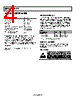
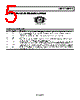
5 / 28 page 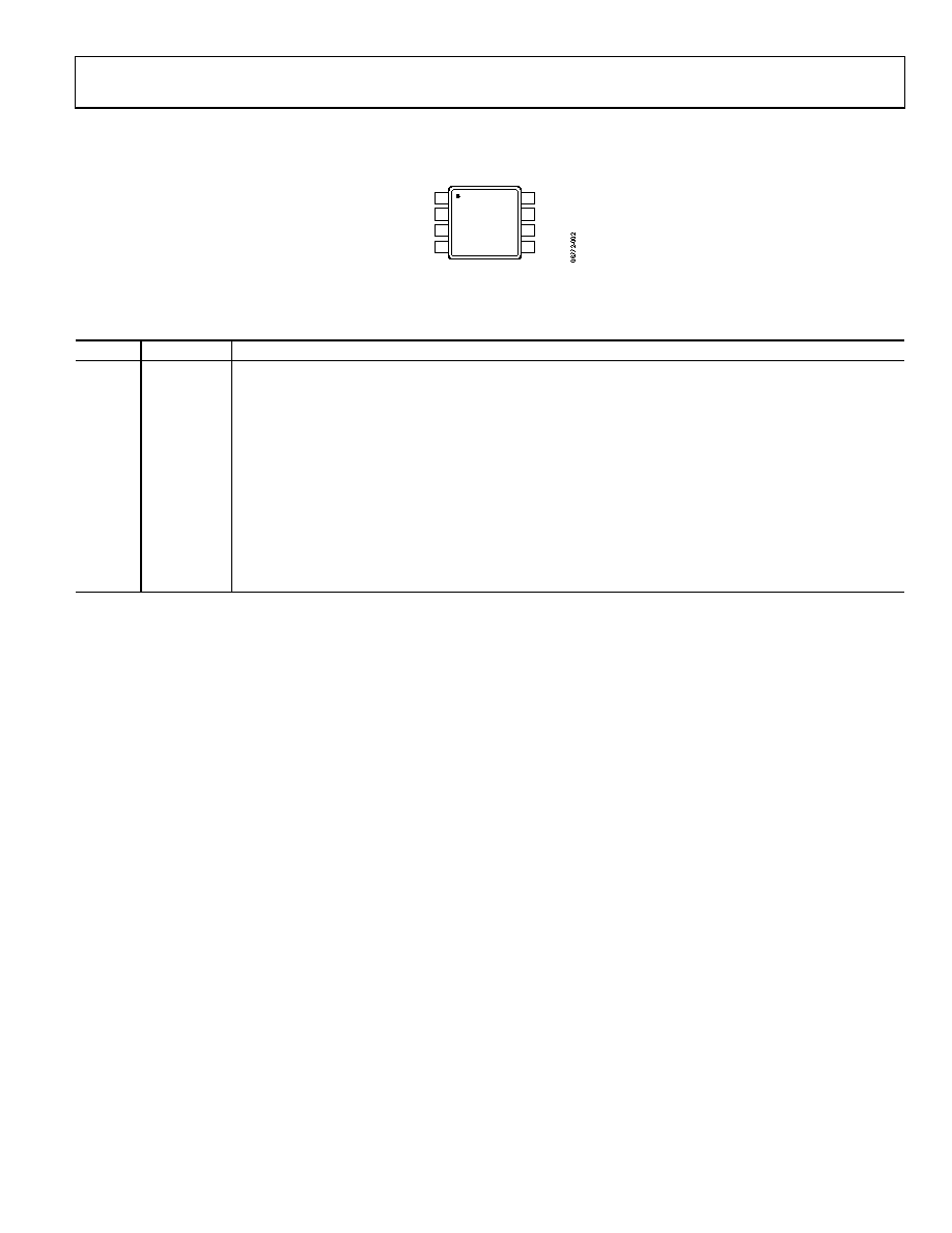 ADP1612/ADP1613 Rev. A | Page 5 of 28 PIN CONFIGURATION AND FUNCTION DESCRIPTIONS COMP 1 FB 2 EN 3 GND 4 SS 8 FREQ 7 VIN 6 SW 5 ADP1612/ ADP1613 TOP VIEW (Not to Scale) Figure 3. Pin Configuration Table 4. Pin Function Descriptions Pin No. Mnemonic Description 1 COMP Compensation Input. Connect a series resistor-capacitor network from COMP to GND to compensate the regulator. 2 FB Output Voltage Feedback Input. Connect a resistive voltage divider from the output voltage to FB to set the regulator output voltage. 3 EN Enable Input. Drive EN low to shut down the regulator; drive EN high to turn on the regulator. 4 GND Ground. 5 SW Switching Output. Connect the power inductor from the input voltage to SW and connect the external rectifier from SW to the output voltage to complete the step-up converter. 6 VIN Main Power Supply Input. VIN powers the ADP1612/ADP1613 internal circuitry. Connect VIN to the input source voltage. Bypass VIN to GND with a 10 μF or greater capacitor as close to the ADP1612/ADP1613 as possible. 7 FREQ Frequency Setting Input. FREQ controls the switching frequency. Connect FREQ to GND to program the oscillator to 650 kHz, or connect FREQ to VIN to program it to 1.3 MHz. If FREQ is left floating, the part defaults to 650 kHz. 8 SS Soft Start Timing Capacitor Input. A capacitor connected from SS to GND brings up the output slowly at power- up and reduces inrush current. |
|
Link URL |
| Does ALLDATASHEET help your business so far? [ DONATE ] |
About Alldatasheet | Advertisement | Contact us | Privacy Policy | Link to Datasheet | Link Exchange | Manufacturer List All Rights Reserved©Alldatasheet.com |
| Russian : Alldatasheetru.com | Korean : Alldatasheet.co.kr | Spanish : Alldatasheet.es | French : Alldatasheet.fr | Italian : Alldatasheetit.com Portuguese : Alldatasheetpt.com | Polish : Alldatasheet.pl | Vietnamese : Alldatasheet.vn Indian : Alldatasheet.in | Mexican : Alldatasheet.com.mx | British : Alldatasheet.co.uk | New Zealand : Alldatasheet.co.nz |
|
Family Site : ic2ic.com |
icmetro.com |
 New Zealand ▼
 English
 Chinese
 German
 Japanese
 Russian
 Korean
 Spanish
 French
 Italian
 Portuguese
 Polish
 Vietnamese
 Indian
 Mexican
 British
 New Zealand