|
Electronic Components Datasheet Search |
|
|
Electronic Components Datasheet Search |
|
ISL6334DIRZ Datasheet(PDF) 26 Page - Intersil Corporation |
|
|
|||||||||||||||||||||||||||||
ISL6334DIRZ Datasheet(HTML) 26 Page - Intersil Corporation |
|
|
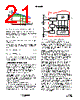
26 / 28 page  26 FN6802.2 August 31, 2010 For a 2-phase design, use Figure 18 to determine the input capacitor RMS current requirement given the duty cycle, maximum sustained output current (IO), and the ratio of the per-phase peak-to-peak inductor current (IL(P-P)) to IO. Select a bulk capacitor with a ripple current rating which will minimize the total number of input capacitors required to support the RMS current calculated. The voltage rating of the capacitors should also be at least 1.25x greater than the maximum input voltage. Figures 19 and 20 provide the same input RMS current information for 3- and 4-phase designs respectively. Use the same approach to selecting the bulk capacitor type and number, as previously described. Low capacitance, high-frequency ceramic capacitors are needed in addition to the bulk capacitors to suppress leading and falling edge voltage spikes. The result from the high current slew rates produced by the upper MOSFETs turn on and off. Select low ESL ceramic capacitors and place one as close as possible to each upper MOSFET drain to minimize board parasitic impedances and maximize suppression. MULTIPHASE RMS IMPROVEMENT Figure 21 is provided as a reference to demonstrate the dramatic reductions in input-capacitor RMS current upon the implementation of the multiphase topology. For example, compare the input RMS current requirements of a 2-phase converter versus that of a single phase. Assume both converters have a duty cycle of 0.25, a maximum sustained output current of 40A, and a ratio of IL(P-P) to IO of 0.5. The single phase converter would require 17.3ARMS current capacity while the two-phase converter would only require 10.9ARMS. The advantages become even more pronounced when output current is increased and additional phases are added to keep the component cost down relative to the single phase approach. Layout Considerations The following layout strategies are intended to minimize the impact of board parasitic impedances on converter performance and to optimize the heat-dissipating capabilities of the printed-circuit board. These sections highlight some important practices which should not be overlooked during the layout process. FIGURE 20. NORMALIZED INPUT-CAPACITOR RMS CURRENT vs DUTY CYCLE FOR 4-PHASE CONVERTER 00.4 1.0 0.2 0.6 0.8 DUTY CYCLE (VO/VIN) 0.3 0.1 0 0.2 IL(P-P) = 0 IL(P-P) = 0.25 IO IL(P-P) = 0.5 IO IL(P-P) = 0.75 IO FIGURE 21. NORMALIZED INPUT-CAPACITOR RMS CURRENT vs DUTY CYCLE FOR SINGLE-PHASE CONVERTER 00.4 1.0 0.2 0.6 0.8 DUTY CYCLE (VO/VIN) 0.6 0.2 0 0.4 IL(P-P) = 0 IL(P-P) = 0.5 IO IL(P-P) = 0.75 IO ISL6334D |
|
Link URL |
| Does ALLDATASHEET help your business so far? [ DONATE ] |
About Alldatasheet | Advertisement | Contact us | Privacy Policy | Link to Datasheet | Link Exchange | Manufacturer List All Rights Reserved©Alldatasheet.com |
| Russian : Alldatasheetru.com | Korean : Alldatasheet.co.kr | Spanish : Alldatasheet.es | French : Alldatasheet.fr | Italian : Alldatasheetit.com Portuguese : Alldatasheetpt.com | Polish : Alldatasheet.pl | Vietnamese : Alldatasheet.vn Indian : Alldatasheet.in | Mexican : Alldatasheet.com.mx | British : Alldatasheet.co.uk | New Zealand : Alldatasheet.co.nz |
|
Family Site : ic2ic.com |
icmetro.com |
 New Zealand ▼
 English
 Chinese
 German
 Japanese
 Russian
 Korean
 Spanish
 French
 Italian
 Portuguese
 Polish
 Vietnamese
 Indian
 Mexican
 British
 New Zealand