|
Electronic Components Datasheet Search |
|
|
Electronic Components Datasheet Search |
|
LD1117SC-R Datasheet(PDF) 25 Page - STMicroelectronics |
|
|
|||||||||||||||||||||||||||||
LD1117SC-R Datasheet(HTML) 25 Page - STMicroelectronics |
|
|
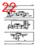
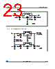
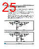
25 / 42 page  LD1117xx LD1117 adjustable: application note Doc ID 2572 Rev 28 25/42 7 LD1117 adjustable: application note The LD1117 adjustable has a thermal stabilized 1.25 ± 0.012 V reference voltage between the OUT and ADJ pins. IADJ is 60 µA typ. (120 µA max.) and ΔIADJ is 1 µA typ. (5 µA max.). R1 is normally fixed to 120 Ω. From Figure 10 we obtain: VOUT = VREF + R2 (IADJ +IR1) = VREF + R2 (IADJ +VREF /R1) = VREF (1 + R2 / R1) + R2 x IADJ. In normal application R2 value is in the range of few kΩ, so the R2 x IADJ product could not be considered in the VOUT calculation; then the above expression becomes: VOUT = VREF (1 + R2 / R1). In order to have the better load regulation it is important to realize a good Kelvin connection of R1 and R2 resistors. In particular R1 connection must be realized very close to OUT and ADJ pin, while R2 ground connection must be placed as near as possible to the negative Load pin. Ripple rejection can be improved by introducing a 10 µF electrolytic capacitor placed in parallel to the R2 resistor (see Figure 11). Figure 11. Adjustable output voltage application Figure 12. Adjustable output voltage application with improved ripple rejection |
|
Link URL |
| Does ALLDATASHEET help your business so far? [ DONATE ] |
About Alldatasheet | Advertisement | Contact us | Privacy Policy | Link to Datasheet | Link Exchange | Manufacturer List All Rights Reserved©Alldatasheet.com |
| Russian : Alldatasheetru.com | Korean : Alldatasheet.co.kr | Spanish : Alldatasheet.es | French : Alldatasheet.fr | Italian : Alldatasheetit.com Portuguese : Alldatasheetpt.com | Polish : Alldatasheet.pl | Vietnamese : Alldatasheet.vn Indian : Alldatasheet.in | Mexican : Alldatasheet.com.mx | British : Alldatasheet.co.uk | New Zealand : Alldatasheet.co.nz |
|
Family Site : ic2ic.com |
icmetro.com |
 New Zealand ▼
 English
 Chinese
 German
 Japanese
 Russian
 Korean
 Spanish
 French
 Italian
 Portuguese
 Polish
 Vietnamese
 Indian
 Mexican
 British
 New Zealand