|
Electronic Components Datasheet Search |
|
|
Electronic Components Datasheet Search |
|
ADP2147ACBZ-130-R7 Datasheet(PDF) 5 Page - Analog Devices |
|
|
|||||||||||||||||||||||||||||
ADP2147ACBZ-130-R7 Datasheet(HTML) 5 Page - Analog Devices |
|
|
5 / 16 page 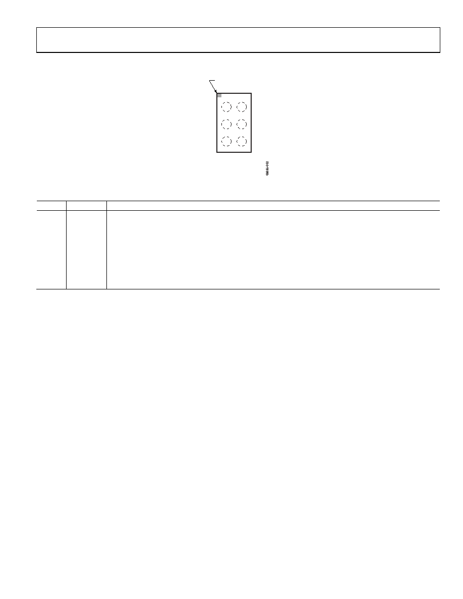 ADP2147 Rev. 0 | Page 5 of 16 PIN CONFIGURATION AND FUNCTION DESCRIPTIONS VIN EN SW GND VOUT VSEL TOP VIEW (BALL SIDE DOWN) Not to Scale ADP2147 1 A B C 2 BALL A1 INDICATOR Figure 2. Pin Configuration (Top View) Table 5. Pin Function Descriptions Pin No. Mnemonic Description A1 VIN Power Source Input. VIN is the source of the pFET high-side switch. Bypass VIN to GND with a 4.7 μF or greater capacitor as close to the ADP2147 as possible. B1 SW Switch Node Output. SW is the drain of the P-channel MOSFET switch and N-channel synchronous rectifier. Connect the output LC filter between SW and the output voltage. C1 GND Ground. Connect the input and output capacitors to GND. A2 EN Buck Activation. To turn on the buck, set EN to high. To turn off the buck, set EN to low. B2 VSEL Voltage Select Input for Simple Dynamic Voltage Scaling (DVS). Drive VSEL low to switch the VOUT pin to the default voltage setting. Drive VSEL high to switch VOUT to the alternate voltage setting. C2 VOUT Output Voltage Sensing Input. |
|
|
Link URL |
| Does ALLDATASHEET help your business so far? [ DONATE ] |
About Alldatasheet | Advertisement | Contact us | Privacy Policy | Link to Datasheet | Link Exchange | Manufacturer List All Rights Reserved©Alldatasheet.com |
| Russian : Alldatasheetru.com | Korean : Alldatasheet.co.kr | Spanish : Alldatasheet.es | French : Alldatasheet.fr | Italian : Alldatasheetit.com Portuguese : Alldatasheetpt.com | Polish : Alldatasheet.pl | Vietnamese : Alldatasheet.vn Indian : Alldatasheet.in | Mexican : Alldatasheet.com.mx | British : Alldatasheet.co.uk | New Zealand : Alldatasheet.co.nz |
|
Family Site : ic2ic.com |
icmetro.com |
 New Zealand ▼
 English
 Chinese
 German
 Japanese
 Russian
 Korean
 Spanish
 French
 Italian
 Portuguese
 Polish
 Vietnamese
 Indian
 Mexican
 British
 New Zealand