|
Electronic Components Datasheet Search |
|
|
Electronic Components Datasheet Search |
|
MC34018L-R28-R Datasheet(PDF) 2 Page - Unisonic Technologies |
|
|
|||||||||||||||||||||||||||||
MC34018L-R28-R Datasheet(HTML) 2 Page - Unisonic Technologies |
|
|
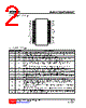
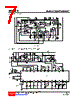
2 / 8 page 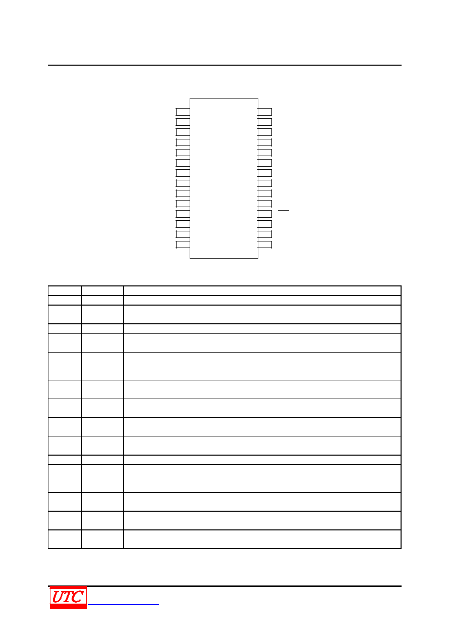 MC34018 LINEAR INTEGRATED CIRCUIT UNISONICTECHNOLOGIESCO.,LTD 2 of 8 www.unisonic.com.tw QW-R108-006,C PIN CONFIGURATION 1 2 3 4 5 6 7 8 9 10 11 12 13 14 28 27 26 25 24 23 22 21 20 19 18 17 16 15 RR RTX TXI TXO TLI TLO RLI RLO MCI MCO CP1 CP2 XDI SKG RRX RXI RXO ACF VLC XDC GND VB VCC SKI CS AGC V+ SKO PIN DESCRIPTION PIN NO. PIN NAME DESCRIPTION 1 RR A resistor to ground provides a reference current for the transmit and receive attenuators 2 RTX A resistor to ground determines the nominal gain of the transmit attenuator, the transmit channel gain is inversely proportional to RTX resistance. 3 TXI Transmit Attenuator Input, Input resistance is nominally 5.0kΩ. 4 TXO Transmit Attenuator Output, The TXO output signal drivers the input of transmit level detcetor, as well as the external circuit which drivers the telephone line. 5 TLI Transmit Level detector Input. An external resistor ac coupled to The TLI pin sets the detection level. Decreasing this resistor increases the sensitivity to transmit channel signals. 6 TLO Transmit Level detector Output. The external resistor and capacitor set the time the comparator will hold the system in the transmit mode after speech ceases. 7 RLI Receive Level detector Input. An external resistor ac coupled to The RLI pin sets the detection level. Decreasing this resistor increases the sensitivity to receive channel signals. 8 RLO Receive Level detector Output. The external resistor and capacitor set the time the comparator will hold the system in the receive mode after speech ceases. 9 MCI Microphone amplifier input. Input impedance is nominally 10kΩ and the dc bias voltage is approximately equal to VB 10 MCO Microphone amplifier output. The MIC amp gain is internally set at 34dB (50V/V). 11 CP1 A parallel resistor and capacitor connected between this pin and VCC holds a voltage corresponding to the background noise level. The transmit detector compares the CP1 voltage with the speech signal from CP2. 12 CP2 A capacitor at this pin peak detects the speech signals for comparison with the background noise level held at CP1. 13 XDI Input to the transmit detector system. The microphone amplifier output is ac coupled to the XDI pin through an external resistor. 14 SKG High current ground pin for the speaker amplifier output stage. The SKG voltage should be within 10mV of the ground voltage at pin 22. |
|
|
Link URL |
| Does ALLDATASHEET help your business so far? [ DONATE ] |
About Alldatasheet | Advertisement | Contact us | Privacy Policy | Link to Datasheet | Link Exchange | Manufacturer List All Rights Reserved©Alldatasheet.com |
| Russian : Alldatasheetru.com | Korean : Alldatasheet.co.kr | Spanish : Alldatasheet.es | French : Alldatasheet.fr | Italian : Alldatasheetit.com Portuguese : Alldatasheetpt.com | Polish : Alldatasheet.pl | Vietnamese : Alldatasheet.vn Indian : Alldatasheet.in | Mexican : Alldatasheet.com.mx | British : Alldatasheet.co.uk | New Zealand : Alldatasheet.co.nz |
|
Family Site : ic2ic.com |
icmetro.com |
 New Zealand ▼
 English
 Chinese
 German
 Japanese
 Russian
 Korean
 Spanish
 French
 Italian
 Portuguese
 Polish
 Vietnamese
 Indian
 Mexican
 British
 New Zealand