 |
Electronic Components Datasheet Search |
|
|
Electronic Components Datasheet Search |
|
CS5490 Datasheet(PDF) 21 Page - Cirrus Logic |
|
|
|||||||||||||||||||||||||||||
CS5490 Datasheet(HTML) 21 Page - Cirrus Logic |
|
|
21 / 56 page 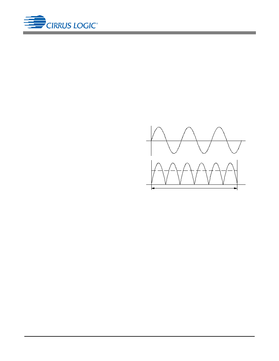 CS5490 DS982F2 21 The CS5490 pulse generation block behaves as follows: • The pulse rate generated by full-scale (1.0 decimal) power register is FOUT =(PulseRate x 2000)/2FREQ_RNG •The PulseRate register value is PulseRate = (FOUT x2FREQ_RNG)/2000 = (18.5186 x 64)/2000 = 0.5925952 = 0x4BDA29 5.5.2 Pulse Width The PulseWidth register defines the Active-low time of each energy pulse: Active-low = 250µs + (PulseWidth/64000). By default, the PulseWidth register value is 1, and the Active-low time of each energy pulse is 265.6µs. Note that the pulse width should never exceed the pulse period. 5.6 Voltage Sag, Voltage Swell, and Overcurrent Detection Voltage sag detection is used to determine when the voltage falls below a predetermined level for a specified interval of time (duration). Voltage swell and overcurrent detection determine when the voltage or current rises above a predetermined level for the duration. The duration is set by the value in the VSagDUR, VSwellDUR, and IOverDUR registers. Setting any of these to zero (default) disables the detect feature for the given channel. The value is in output word rate (OWR) samples. The predetermined level is set by the values in the VSagLEVEL, VSwellLEVEL, and IOverLEVEL registers. For each enabled input channel, the measured value is rectified and compared to the associated level register. Over the duration window, the number of samples above and below the level are counted. If the number of samples below the level exceeds the number of samples above, a Status0 register bit VSAG is set, indicating a sag condition. If the number of samples above the level exceeds the number of samples below, a Status0 register bit VSWELL or IOVER is set, indicating a swell or overcurrent condition (see Figure 11). Lev e l Du ra tio n Figure 11. Sag, Swell, & Overcurrent Detect |
|
Link URL |
| Does ALLDATASHEET help your business so far? [ DONATE ] |
About Alldatasheet | Advertisement | Contact us | Privacy Policy | Link to Datasheet | Link Exchange | Manufacturer List All Rights Reserved©Alldatasheet.com |
| Russian : Alldatasheetru.com | Korean : Alldatasheet.co.kr | Spanish : Alldatasheet.es | French : Alldatasheet.fr | Italian : Alldatasheetit.com Portuguese : Alldatasheetpt.com | Polish : Alldatasheet.pl | Vietnamese : Alldatasheet.vn Indian : Alldatasheet.in | Mexican : Alldatasheet.com.mx | British : Alldatasheet.co.uk | New Zealand : Alldatasheet.co.nz |
|
Family Site : ic2ic.com |
icmetro.com |
 New Zealand ▼
 English
 Chinese
 German
 Japanese
 Russian
 Korean
 Spanish
 French
 Italian
 Portuguese
 Polish
 Vietnamese
 Indian
 Mexican
 British
 New Zealand


