|
Electronic Components Datasheet Search |
|
|
Electronic Components Datasheet Search |
|
MCP1640 Datasheet(PDF) 17 Page - Microchip Technology |
|
|
|||||||||||||||||||||||||||||
MCP1640 Datasheet(HTML) 17 Page - Microchip Technology |
|
|
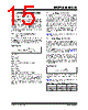
17 / 32 page  2011 Microchip Technology Inc. DS22234B-page 17 MCP1640/B/C/D The feedback resistors and feedback signal should be routed away from the switching node and the switching current loop. When possible, ground planes and traces should be used to help shield the feedback signal and minimize noise and magnetic interference. FIGURE 5-1: MCP1640/B/C/D SOT23-6 Recommended Layout. FIGURE 5-2: MCP1640/B/C/D DFN-8 Recommended Layout. COUT L CIN +VIN GND GND +VOUT Via to GND Plane MCP1640 Via for Enable RTOP RBOT 1 COUT L CIN +VIN GND +VOUT MCP1640 Enable RTOP RBOT GND Wired on Bottom Plane 1 |
|
Link URL |
| Does ALLDATASHEET help your business so far? [ DONATE ] |
About Alldatasheet | Advertisement | Contact us | Privacy Policy | Link to Datasheet | Link Exchange | Manufacturer List All Rights Reserved©Alldatasheet.com |
| Russian : Alldatasheetru.com | Korean : Alldatasheet.co.kr | Spanish : Alldatasheet.es | French : Alldatasheet.fr | Italian : Alldatasheetit.com Portuguese : Alldatasheetpt.com | Polish : Alldatasheet.pl | Vietnamese : Alldatasheet.vn Indian : Alldatasheet.in | Mexican : Alldatasheet.com.mx | British : Alldatasheet.co.uk | New Zealand : Alldatasheet.co.nz |
|
Family Site : ic2ic.com |
icmetro.com |
 New Zealand ▼
 English
 Chinese
 German
 Japanese
 Russian
 Korean
 Spanish
 French
 Italian
 Portuguese
 Polish
 Vietnamese
 Indian
 Mexican
 British
 New Zealand