 |
Electronic Components Datasheet Search |
|
|
Electronic Components Datasheet Search |
|
ADT7316ARQZ Datasheet(PDF) 21 Page - Analog Devices |
|
|
|||||||||||||||||||||||||||||
ADT7316ARQZ Datasheet(HTML) 21 Page - Analog Devices |
|
|
21 / 44 page 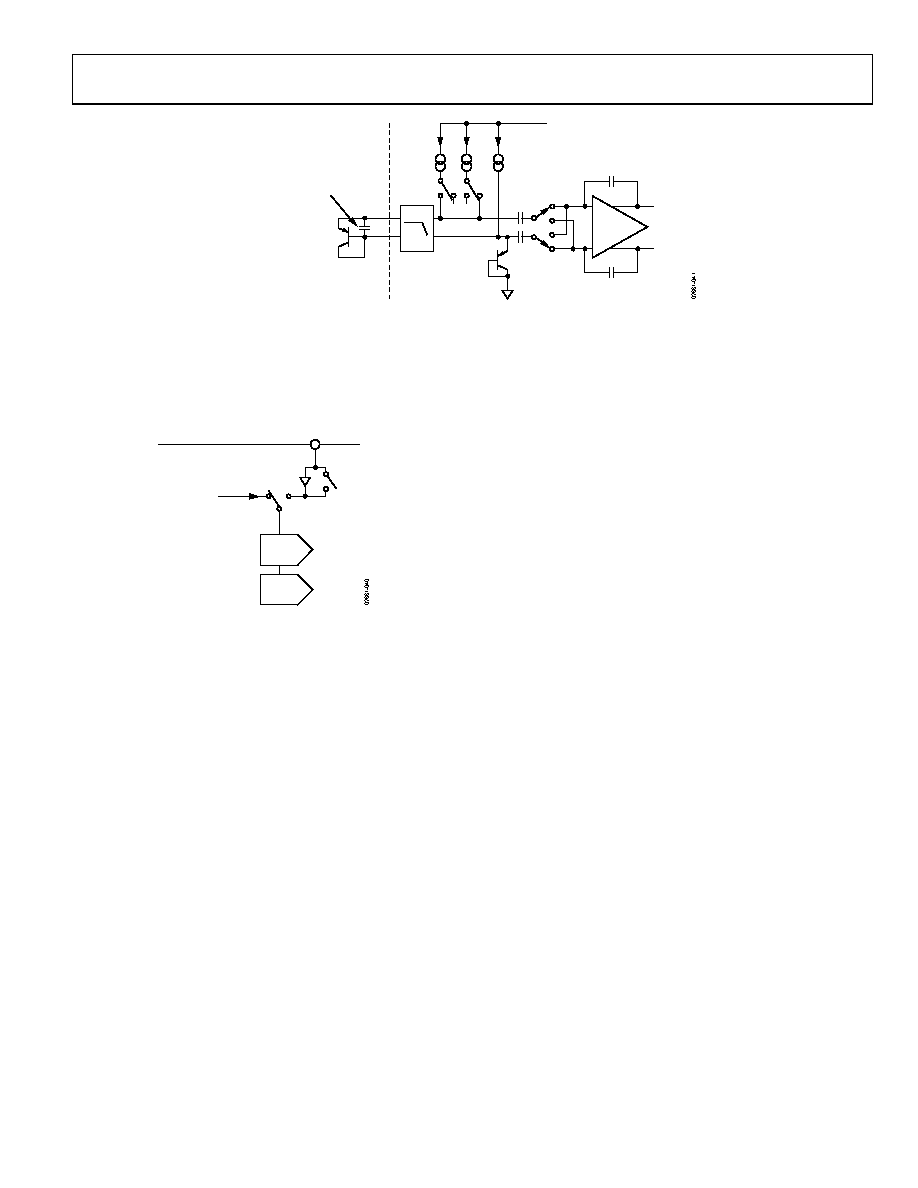 ADT7316/ADT7317/ADT7318 Rev. B | Page 21 of 44 C1 D+ LOW-PASS FILTER fC = 65kHz BIAS DIODE VDD TO ADC VOUT+ VOUT– REMOTE SENSING TRANSISTOR (2N3906) OPTIONAL CAPACITOR, UP TO 3nF MAX. CAN BE ADDED TO IMPROVE HIGH FREQUENCY NOISE REJECTION IN NOISY ENVIRONMENTS D– I N × I IBIAS Figure 41. Signal Conditioning for External Diode Temperature Sensors The buffered/unbuffered option is controlled by the DAC Configuration register (Address 0x1B; see the Registers section). The LDAC Configuration register controls the selection between internal and external voltage references. The default setting is for external reference to be selected. STRING DAC A STRING DAC B VREF-AB 2.25V INTERNAL VREF Figure 42. DAC Reference Buffer Circuit OUTPUT AMPLIFIER The output buffer amplifier is capable of generating output voltages to within 1 mV of either rail. Its actual range depends on the value of VREF, gain, and offset error. If a gain of 1 is selected (Bit 0 to Bit 3 = 0, DAC Configuration register, Address 0x1B), the output range is 0.001 V to VREF. If a gain of 2 is selected (Bit 0 to Bit 3 = 1, DAC Configuration register, Address 0x1B), the output range is 0.001 V to 2 VREF. Because of clamping, however, the maximum output is limited to VDD – 0.001 V. The output amplifier is capable of driving a load of 4.7 kΩ to VDD or 4.7 kΩ to GND in parallel with 200 pF to GND (see Figure 6). The source and sink capabilities of the output amplifier can be seen in Figure 20. The slew rate is 0.7 V/μs with a half-scale settling time to ±0.5 LSB (at 8 bits) of 6 μs. THERMAL VOLTAGE OUTPUT The ADT7316/ADT7317/ADT7318 are capable of outputting voltages that are proportional to temperature. The DAC A output can be configured to represent the temperature of the internal sensor while DAC B output can be configured to represent the external temperature sensor. Bit C5 and Bit C6 of the Control Configuration 3 register select the temperature proportional to output voltage. Each time a temperature measurement is taken, the DAC output is updated. The out- put resolution for the ADT7318 is 8 bits with the 1°C change corresponding to the 1 LSB change. The output resolution for the ADT7316 and ADT7317 is capable of 10 bits with a 0.25°C change corresponding to the 1 LSB change. The default output resolution for the ADT7316 and ADT7317 is 8 bits. To increase this to 10 bits, set C1 = 1 of the Control Configuration 3 register (Address 0x1A). The default output range is 0 V to VREF-AB, and this can be increased to 0 V to 2 VREF-AB. The user can select the internal VREF (VREF = 2.28 V) by setting D4 = 1 in the LDAC Configuration register (Address 0x1C). Increasing the output voltage span to 2 VREF can be done by setting D0 = 1 for DAC A (internal temperature sensor), and D1 = 1 for DAC B (external temperature sensor) in the DAC Configuration register (Address 0x1B). The output voltage is capable of tracking a maximum tem- perature range of −128°C to +127°C, but the default setting is −40°C to +127°C. If the output voltage range is 0 V to VREF-AB (VREF-AB = 2.25 V), then this corresponds to 0 V representing −40°C, and 1.48 V representing +127°C. This gives an upper dead band between 1.48 V and VREF-AB. The internal and external analog temperature offset registers can be used to vary this upper dead band, and consequently, the temperature that 0 V corresponds to. Table 6 and Table 7 give examples of how this is done using a DAC output voltage span of VREF and 2 VREF, respectively. Write in the temperature value, in twos complement format, at which 0 V is to start. For example, if using the DAC A output with 0 V to start at −40°C, program 0xD8 into the internal analog temperature offset regis- ter (Address 0x21). This is an 8-bit register, and thus, only has a temperature offset resolution of 1°C for all device models. Use the following formulas to determine the value to program into the offset registers. |
|
Link URL |
| Does ALLDATASHEET help your business so far? [ DONATE ] |
About Alldatasheet | Advertisement | Contact us | Privacy Policy | Link to Datasheet | Link Exchange | Manufacturer List All Rights Reserved©Alldatasheet.com |
| Russian : Alldatasheetru.com | Korean : Alldatasheet.co.kr | Spanish : Alldatasheet.es | French : Alldatasheet.fr | Italian : Alldatasheetit.com Portuguese : Alldatasheetpt.com | Polish : Alldatasheet.pl | Vietnamese : Alldatasheet.vn Indian : Alldatasheet.in | Mexican : Alldatasheet.com.mx | British : Alldatasheet.co.uk | New Zealand : Alldatasheet.co.nz |
|
Family Site : ic2ic.com |
icmetro.com |
 New Zealand ▼
 English
 Chinese
 German
 Japanese
 Russian
 Korean
 Spanish
 French
 Italian
 Portuguese
 Polish
 Vietnamese
 Indian
 Mexican
 British
 New Zealand


