 |
Electronic Components Datasheet Search |
|
|
Electronic Components Datasheet Search |
|
CSTCC2M00G53-R0 Datasheet(PDF) 25 Page - Murata Manufacturing Co., Ltd. |
|
|
|||||||||||||||||||||||||||||
CSTCC2M00G53-R0 Datasheet(HTML) 25 Page - Murata Manufacturing Co., Ltd. |
|
|
25 / 32 page 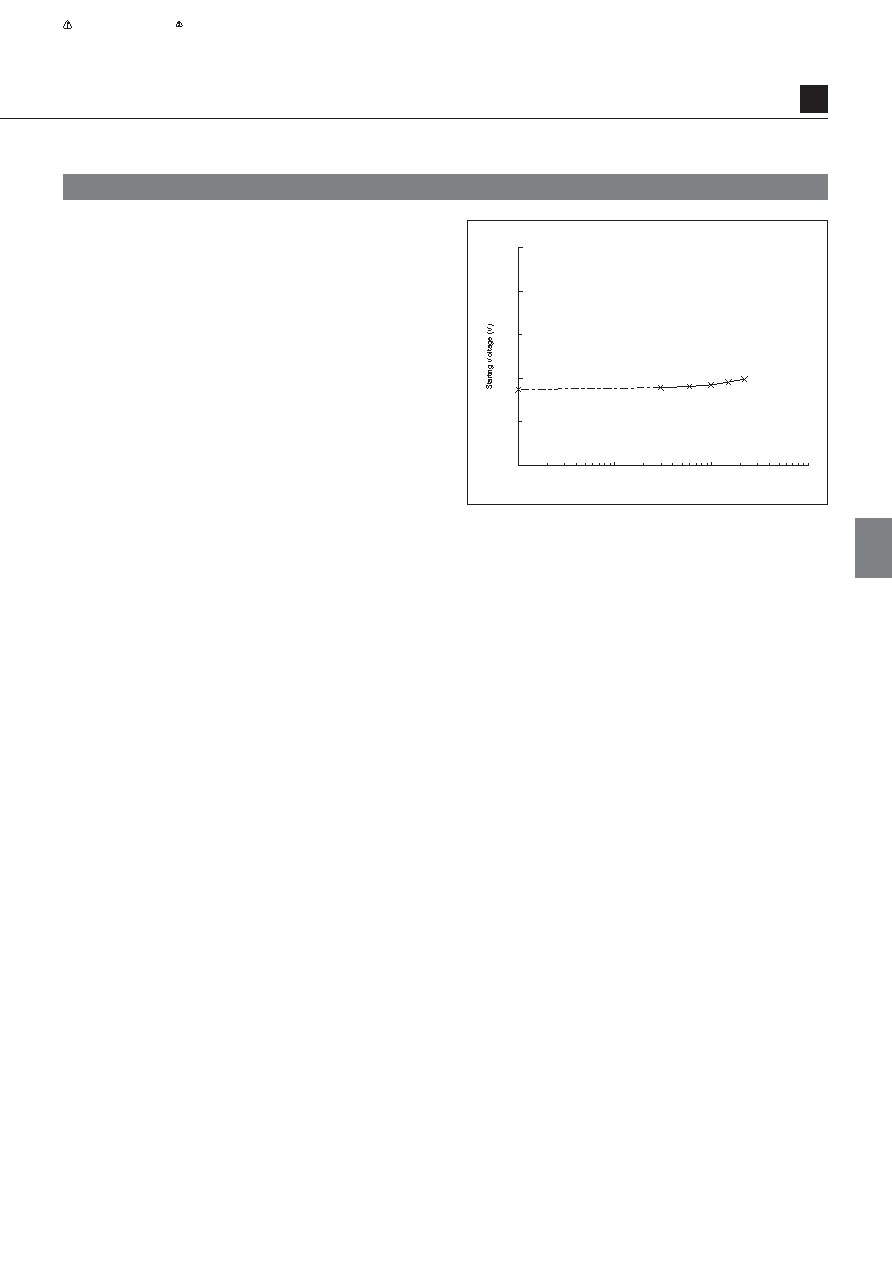 23 Note • Please read rating and CAUTION (for storage, operating, rating, soldering, mounting and handling) in this catalog to prevent smoking and/or burning, etc. • This catalog has only typical specifications because there is no space for detailed specifications. Therefore, please review our product specifications or consult the approval sheet for product specifications before ordering. 4. Starting Voltage Starting voltage refer to the minimum supply voltage at which an oscillation circuit can operate. Starting voltage is affected by all the circuit elements, but it is determined mostly by the characteristics of the IC. Fig. 5-6 shows an example of an actual measurement for the starting voltage characteristics against the loading capacitance. Fig. 5-6 Starting Voltage Characteristics against CL (CL1=CL2) (IC: TC74HCU04 (TOSHIBA), CERALOCK®: CSACW33M8X51–B0) 0 0 1.0 2.0 3.0 4.0 5.0 110 100 CL (pF) VDD = +5V 5 5 Characteristics of CERALOCK® Oscillation Circuits P17E.pdf 2012.10.31 |
|
Link URL |
| Does ALLDATASHEET help your business so far? [ DONATE ] |
About Alldatasheet | Advertisement | Contact us | Privacy Policy | Link to Datasheet | Link Exchange | Manufacturer List All Rights Reserved©Alldatasheet.com |
| Russian : Alldatasheetru.com | Korean : Alldatasheet.co.kr | Spanish : Alldatasheet.es | French : Alldatasheet.fr | Italian : Alldatasheetit.com Portuguese : Alldatasheetpt.com | Polish : Alldatasheet.pl | Vietnamese : Alldatasheet.vn Indian : Alldatasheet.in | Mexican : Alldatasheet.com.mx | British : Alldatasheet.co.uk | New Zealand : Alldatasheet.co.nz |
|
Family Site : ic2ic.com |
icmetro.com |
 New Zealand ▼
 English
 Chinese
 German
 Japanese
 Russian
 Korean
 Spanish
 French
 Italian
 Portuguese
 Polish
 Vietnamese
 Indian
 Mexican
 British
 New Zealand


