 |
Electronic Components Datasheet Search |
|
|
Electronic Components Datasheet Search |
|
EALED78X64-R Datasheet(PDF) 5 Page - List of Unclassifed Manufacturers |
|
|
|||||||||||||||||||||||||||||
EALED78X64-R Datasheet(HTML) 5 Page - List of Unclassifed Manufacturers |
|
|
5 / 9 page 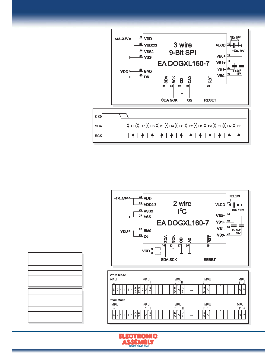 EADOG XL160-7 Page 5 ELECTRONIC ASSEMBLY reserves the right to change specifications without prior notice. Printing and typographical errors reserved. 2 WIRE, I2C-MODE Pin A2 is used to configure the device address. Each I²C sequence starts with a START condition (S) from the bus master, followed by a sequence header, containing a device address, the mode of transfer (CD: 0=Control, 1=Data), and the direction of the transfer (RW: 0=Write, 1=Read). Note that, for data read (CD=1), the first byte of data transmitted will be dummy. The direction (read or write) and content type (command or data) of the data bytes following each header byte are fixed for the sequence. To change the direction (R<>W) or the content type (C<>D), start a new sequence with a START (S) flag, followed by a new header. The clock-pulse rate of the SCK line can be up to 4 MHz. Note that, for choosing your pullups, the SDA and SCK pins do have an internal resistance of 600...1000 Ohm or more (control LO-level when reading e.g. ACK-bit). 3 WIRE, 9-BIT SPI-MODE Pin CS0 is used for chip select and bus cycle reset. On each write cycle, the first bit is CD, which determines the content of the following 8 bits of data, MSB first.These 8 command or data bits are latched on rising SCK edges into an 8-bit data holder. If CD=0, the data byte will be decoded as command. If CD=1, this 8-bit will be treated as data and transferred to proper address in the Display Data RAM at the rising edgeof the last SCK pulse. The toggle of CS0 for each byte of data/ command is recommended but optional.The clock-pulse rate of the SCK line can be up to 12 MHz. I2C-Address (A2=LO) Adr Function $78 Write Command $79 Read Status $7A Write Data $7B Read Data I2C-Address (A2=HI) Adr Function $7C Write Command $7D Read Status $7E Write Data $7F Read Data |
|
|
Link URL |
| Does ALLDATASHEET help your business so far? [ DONATE ] |
About Alldatasheet | Advertisement | Contact us | Privacy Policy | Link to Datasheet | Link Exchange | Manufacturer List All Rights Reserved©Alldatasheet.com |
| Russian : Alldatasheetru.com | Korean : Alldatasheet.co.kr | Spanish : Alldatasheet.es | French : Alldatasheet.fr | Italian : Alldatasheetit.com Portuguese : Alldatasheetpt.com | Polish : Alldatasheet.pl | Vietnamese : Alldatasheet.vn Indian : Alldatasheet.in | Mexican : Alldatasheet.com.mx | British : Alldatasheet.co.uk | New Zealand : Alldatasheet.co.nz |
|
Family Site : ic2ic.com |
icmetro.com |
 New Zealand ▼
 English
 Chinese
 German
 Japanese
 Russian
 Korean
 Spanish
 French
 Italian
 Portuguese
 Polish
 Vietnamese
 Indian
 Mexican
 British
 New Zealand


