 |
Electronic Components Datasheet Search |
|
|
Electronic Components Datasheet Search |
|
STLED25 Datasheet(PDF) 20 Page - STMicroelectronics |
|
|
|||||||||||||||||||||||||||||
STLED25 Datasheet(HTML) 20 Page - STMicroelectronics |
|
|
20 / 30 page 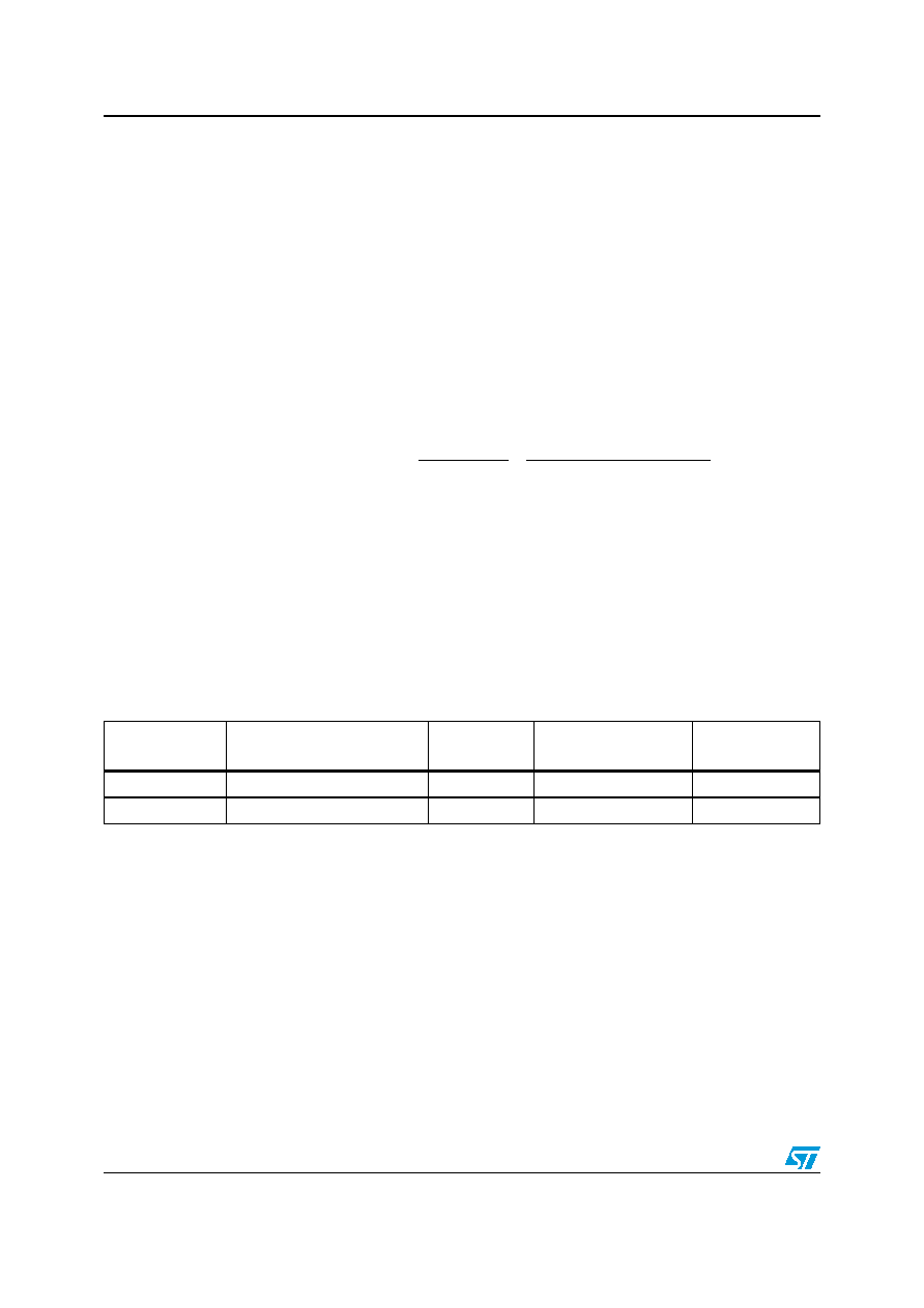 Application information STLED25 20/30 Doc ID 022323 Rev 3 7 Application information 7.1 External passive components 7.1.1 Inductor selection The inductor is the key passive component for switching converters. For the STLED25, an inductance of 4.7 µH is recommended. It is very important to select the right inductor according to the maximum current the inductor can handle to avoid saturation. The peak current for the step-up can be calculated with the following formula: Equation 2 where: VOUT: step-up output voltage. The boost control loop keeps it 135 mV higher than the maximum among VD1-D5 IOUT: total output current VIN: input voltage of STLED25 fs: switching frequency. Use the minimum value of 2.25 MHz for the worst case η: efficiency of step-up converter. It is 0.87 at 75 mA load 7.1.2 Input and output capacitor selection It is recommended to use ceramic capacitors with low ESR as input and output capacitors in order to filter any disturbance present in the input line and to maintain stable operation of the step-up converter. A minimum real capacitance value of 1 µF must be guaranteed for CIN and 4.2 µF COUT in all conditions. L fs V 2 ) VIN V ( VIN VIN I V I OUT MIN OUT MIN MIN OUT OUT BOOST PEAK × × × − × + × η × = − Table 7. List of recommended inductors Manufacturer Part number Inductance [µH] Saturation current [A] Size [mm] Samsung CIG21K4R7SCE 4.7 0.6 0805 Murata LQM21PN4R7 4.7 0.6 0805 |
|
Link URL |
| Does ALLDATASHEET help your business so far? [ DONATE ] |
About Alldatasheet | Advertisement | Contact us | Privacy Policy | Link to Datasheet | Link Exchange | Manufacturer List All Rights Reserved©Alldatasheet.com |
| Russian : Alldatasheetru.com | Korean : Alldatasheet.co.kr | Spanish : Alldatasheet.es | French : Alldatasheet.fr | Italian : Alldatasheetit.com Portuguese : Alldatasheetpt.com | Polish : Alldatasheet.pl | Vietnamese : Alldatasheet.vn Indian : Alldatasheet.in | Mexican : Alldatasheet.com.mx | British : Alldatasheet.co.uk | New Zealand : Alldatasheet.co.nz |
|
Family Site : ic2ic.com |
icmetro.com |
 New Zealand ▼
 English
 Chinese
 German
 Japanese
 Russian
 Korean
 Spanish
 French
 Italian
 Portuguese
 Polish
 Vietnamese
 Indian
 Mexican
 British
 New Zealand


