 |
Electronic Components Datasheet Search |
|
|
Electronic Components Datasheet Search |
|
ADL5315ACPZ-R7 Datasheet(PDF) 15 Page - Analog Devices |
|
|
|||||||||||||||||||||||||||||
ADL5315ACPZ-R7 Datasheet(HTML) 15 Page - Analog Devices |
|
|
15 / 17 page 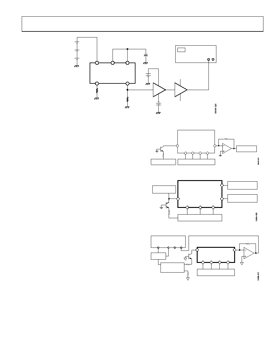 Data Sheet ADL5315 Rev. A | Page 15 of 17 RINPUT FET BUFFER VECTOR SIGNAL ANALYZER HP89410A ADL5315 VPOS SREF VSET +12V –12V INPT IOUT RLOAD 2.2nF LNA 1.5V + – + – 1.5V 9V + – 1.5V + – – + 9V Figure 31. Configuration for Noise Spectral Density and Wideband Current Noise Figure 32 shows the configuration used to measure the pulse response of IINPT to IOUT. To create the test current pulse, Q1 is used in a common base configuration with the Agilent 33250A pulse generator. The output of the 33250A is a negative biased square wave with an amplitude that results in a one decade current step at IOUT. RC is chosen according to what current range is desired. For 30 µA and lower, the AD8067 FET input op amp is used in a transimpedance amplifier configuration to allow for viewing on the TDS5104 oscilloscope. For signals greater than 30 µA, the ADA4899-1 replaced the AD8067 to avoid limiting the bandwidth of the ADL5315. The configuration in Figure 33 is used to measure VINPT while VSET is pulsed. Q1 and RC are used to generate the operating current on the INPT pin. An Agilent 33250A pulse generator is used on the VSET pin to create a 0.0 V to 4.0 V square wave. The setup in Figure 34 was used to measure the small signal ac response from IINPT to IOUT. The AD8138 differential amplifier was used to couple the ac and dc signals together. The ac signal was modulated to a depth of 5% of full scale over frequency. The voltage across RF sets the dc operating point of IINPT. The values of RF are chosen to result in decade changes in IINPT. The ADA4899-1 op amp is used as a transimpedance amplifier for all current conditions. TDS5104 OSCILLOSCOPE ADL5315 EVALUATION BOARD INPT VPOS VSET SREF COMM IOUT DC SUPPLIES/DMM RC RC AGILENT 33250A PULSE GENERATOR Q1 Figure 32. Configuration for Pulse Response of IINPT to IOUT RC Q1 TDS5104 OSCILLOSCOPE ADL5315 EVALUATION BOARD VPOS SREF COMM IOUT DC SUPPLIES/DMM INPT VSET AGILENT 33250A PULSE GENERATOR KEITHLEY 236 Figure 33. Configuration for Pulse Response from VSET to VINPT NETWORK ANALYZER OUTPUT R B A POWER SPLITTER AD8138 EVAL BOARD + + – – ADL5315 EVALUATION BOARD INPT 50 Ω IOUT RF RF VPOS VSET SREF COMM DC SUPPLIES/DMM Figure 34. Configuration for Small-Signal AC Response |
|
|
Link URL |
| Does ALLDATASHEET help your business so far? [ DONATE ] |
About Alldatasheet | Advertisement | Contact us | Privacy Policy | Link to Datasheet | Link Exchange | Manufacturer List All Rights Reserved©Alldatasheet.com |
| Russian : Alldatasheetru.com | Korean : Alldatasheet.co.kr | Spanish : Alldatasheet.es | French : Alldatasheet.fr | Italian : Alldatasheetit.com Portuguese : Alldatasheetpt.com | Polish : Alldatasheet.pl | Vietnamese : Alldatasheet.vn Indian : Alldatasheet.in | Mexican : Alldatasheet.com.mx | British : Alldatasheet.co.uk | New Zealand : Alldatasheet.co.nz |
|
Family Site : ic2ic.com |
icmetro.com |
 New Zealand ▼
 English
 Chinese
 German
 Japanese
 Russian
 Korean
 Spanish
 French
 Italian
 Portuguese
 Polish
 Vietnamese
 Indian
 Mexican
 British
 New Zealand


