|
Electronic Components Datasheet Search |
|
|
Electronic Components Datasheet Search |
|
UC3863AL-SH2-R Datasheet(PDF) 7 Page - Unisonic Technologies |
|
|
|||||||||||||||||||||||||||||
UC3863AL-SH2-R Datasheet(HTML) 7 Page - Unisonic Technologies |
|
|
7 / 10 page 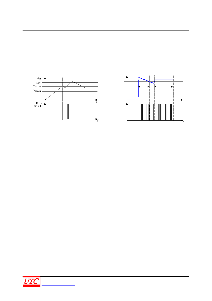 UC3863A LINEAR INTEGRATED CIRCUIT UNISONICTECHNOLOGIESCO.,LTD 7 of 10 www.unisonic.com.tw QW-R103-148.B OPERATION DESCRIPTION (Cont.) Protection Controls The IC takes on more protection functions such as OVP, OLP and OTP etc. In case of those failure modes for continual blanking time, the driver is shut down. Driver is reset after failure is eliminated. OVP The OVP will shut down the switching of the power MOSFET whenever VDD >VOVP. The OVP event as followed Fig.3. VFB Driver ON / OFF t t VFB(IN) VOLP T1<TDelay T2=TDelay Fig.3 OVP case Fig.4 OLP case OLP OLP will shut down driver when VFB> VOLP for continual a blanking time. The OLP event as followed Fig.4. OTP OTP will shut down driver when junction temperature TJ>T (THR). PCB Layout Note Noise from the current sense or the control signal can cause significant pulse width jitter in continuous-conduction mode, and slope compensation helps alleviate these problems. Good placement and layout practices should be followed. Avoiding long PCB traces and component leads, locating compensation and filter components near the UC3863A, and increasing the power MOS gate resistance is advised. |
|
|
Link URL |
| Does ALLDATASHEET help your business so far? [ DONATE ] |
About Alldatasheet | Advertisement | Contact us | Privacy Policy | Link to Datasheet | Link Exchange | Manufacturer List All Rights Reserved©Alldatasheet.com |
| Russian : Alldatasheetru.com | Korean : Alldatasheet.co.kr | Spanish : Alldatasheet.es | French : Alldatasheet.fr | Italian : Alldatasheetit.com Portuguese : Alldatasheetpt.com | Polish : Alldatasheet.pl | Vietnamese : Alldatasheet.vn Indian : Alldatasheet.in | Mexican : Alldatasheet.com.mx | British : Alldatasheet.co.uk | New Zealand : Alldatasheet.co.nz |
|
Family Site : ic2ic.com |
icmetro.com |
 New Zealand ▼
 English
 Chinese
 German
 Japanese
 Russian
 Korean
 Spanish
 French
 Italian
 Portuguese
 Polish
 Vietnamese
 Indian
 Mexican
 British
 New Zealand