|
Electronic Components Datasheet Search |
|
|
Electronic Components Datasheet Search |
|
M95512-R Datasheet(PDF) 9 Page - STMicroelectronics |
|
|
|||||||||||||||||||||||||||||
M95512-R Datasheet(HTML) 9 Page - STMicroelectronics |
|
|
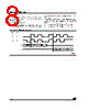
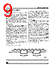
9 / 31 page 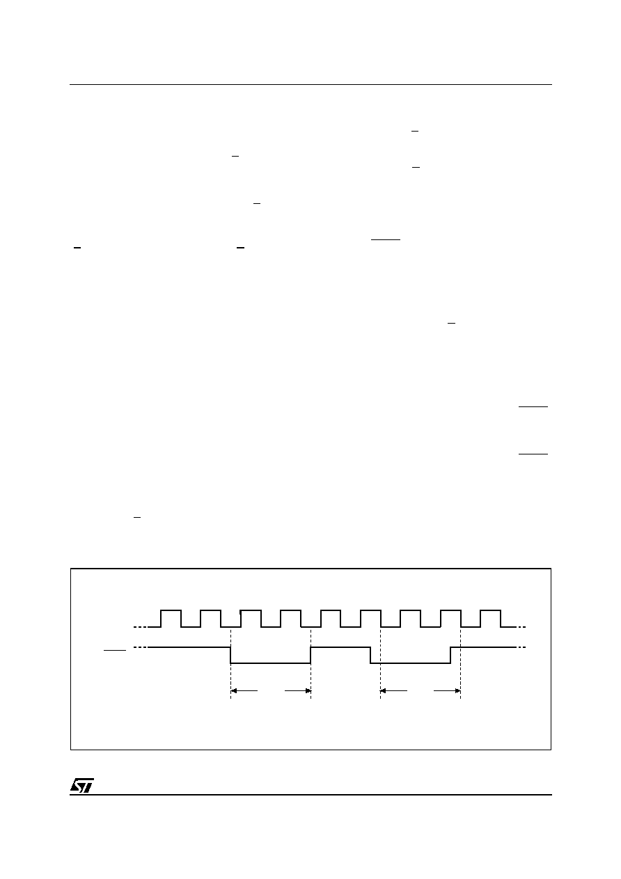 9/31 M95512-W, M95512-R OPERATING FEATURES Power-up When the power supply is turned on, VCC rises from VSS to VCC. During this time, the Chip Select (S) must be al- lowed to follow the VCC voltage. It must not be al- lowed to float, but should be connected to VCC via a suitable pull-up resistor. As a built in safety feature, Chip Select (S) is edge sensitive as well as level sensitive. After Power- up, the device does not become selected until a falling edge has first been detected on Chip Select (S). This ensures that Chip Select (S) must have been High, prior to going Low to start the first op- eration. Power On Reset In order to prevent inadvertent Write operations during Power-up, a Power On Reset (POR) circuit is included. At Power-up, the device will not re- spond to any instruction until the VCC has reached the Power On Reset threshold voltage (this thresh- old is lower than the VCC min operating voltage defined in Table 8. and Table 9.). In the same way, as soon as VCC drops from the normal operating voltage to below the Power On Reset threshold voltage, the device stops responding to any in- struction sent to it. Prior to selecting and issuing instructions to the memory, a valid and stable VCC voltage must be applied. This voltage must remain stable and valid until the end of the transmission of the instruction and, for a Write instruction, until the completion of the internal write cycle (tW). Power-down At Power-down, the device must be deselected. Chip Select (S) should be allowed to follow the voltage applied on VCC. Active Power and Standby Power Modes When Chip Select (S) is Low, the device is select- ed, and in the Active Power mode. The device consumes ICC, as specified in Table 13. When Chip Select (S) is High, the device is dese- lected. If an Erase/Write cycle is not currently in progress, the device then goes in to the Standby Power mode, and the device consumption drops to ICC1. Hold Condition The Hold (HOLD) signal is used to pause any se- rial communications with the device without reset- ting the clocking sequence. During the Hold condition, the Serial Data Output (Q) is high impedance, and Serial Data Input (D) and Serial Clock (C) are Don’t Care. To enter the Hold condition, the device must be selected, with Chip Select (S) Low. Normally, the device is kept selected, for the whole duration of the Hold condition. Deselecting the de- vice while it is in the Hold condition, has the effect of resetting the state of the device, and this mech- anism can be used if it is required to reset any pro- cesses that had been in progress. The Hold condition starts when the Hold (HOLD) signal is driven Low at the same time as Serial Clock (C) already being Low (as shown in Figure 6.). The Hold condition ends when the Hold (HOLD) signal is driven High at the same time as Serial Clock (C) already being Low. Figure 6. also shows what happens if the rising and falling edges are not timed to coincide with Serial Clock (C) being Low. Figure 6. Hold Condition Activation AI02029D HOLD C Hold Condition Hold Condition |
|
Link URL |
| Does ALLDATASHEET help your business so far? [ DONATE ] |
About Alldatasheet | Advertisement | Contact us | Privacy Policy | Link to Datasheet | Link Exchange | Manufacturer List All Rights Reserved©Alldatasheet.com |
| Russian : Alldatasheetru.com | Korean : Alldatasheet.co.kr | Spanish : Alldatasheet.es | French : Alldatasheet.fr | Italian : Alldatasheetit.com Portuguese : Alldatasheetpt.com | Polish : Alldatasheet.pl | Vietnamese : Alldatasheet.vn Indian : Alldatasheet.in | Mexican : Alldatasheet.com.mx | British : Alldatasheet.co.uk | New Zealand : Alldatasheet.co.nz |
|
Family Site : ic2ic.com |
icmetro.com |
 New Zealand ▼
 English
 Chinese
 German
 Japanese
 Russian
 Korean
 Spanish
 French
 Italian
 Portuguese
 Polish
 Vietnamese
 Indian
 Mexican
 British
 New Zealand