|
Electronic Components Datasheet Search |
|
|
Electronic Components Datasheet Search |
|
STEC01 Datasheet(PDF) 8 Page - STMicroelectronics |
|
|
|||||||||||||||||||||||||||||
STEC01 Datasheet(HTML) 8 Page - STMicroelectronics |
|
|
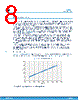
8 / 22 page  6 General description The STEC01 is an integrated low-side 12 mΩ N-channel power MOSFET used to protect applications where a big amount of current flows from the battery to an actuator such as the heater inside an e-cigarette. The maximum on-time can be configured for the actuator with a range from 5 s to 20480 s. Once the set time expires, the actuator is disconnected from the GND path. The device monitors the PWM activity and as soon as a rising edge is detected it exits the idle mode, turns the N- channel power MOSFET on to connect the actuator to the GND path and starts the setting on-time timer (T1). As soon as a falling edge on PWM is detected, a 285 ms timer (T2) is started and, if within such time no further PWM activity is recognized, the N-channel MOSFET is turned off and the device enters idle mode till a new PWM signal is detected (Figure 6. T1 vs RTPF- prescaler x1). Depending on the user's application, the device works with a continuous or pulsed PWM signal. If, for any reason, the PWM duration is longer than the value set for timer T1, a fault event is detected, the N- channel MOSFET is turned off and a fault signal is generated. In order to exit fault mode, a stable low voltage level on the PWM pin is required. Once the PWM goes low, T2 starts counting about 250 ms to make sure the fault has been removed and as soon as it expires, the T3 timer is started. Timer T3 sets the cooling window during which any new activity on the PWM pin is ignored and the internal N-channel power MOSFET is kept OFF (T3 can be programmed to 69 s, 345 s or 1380 s). Once T3 expires, a new power cycle can be started by a valid PWM signal. The STEC01 is able to manage a continuous current up to 7 A through the internal power MOSFET. A higher current can be supported by using an external N-channel power MOSFET driven through GDRV pin. A rising edge on the HW_RESET input pin generates a 57 ms pulse on the RESET_FAULT pin that can be detected by a dedicated MCU GPIO. This function can be used to notify the connection of an external power source (e.g. USB). 6.1 T1 timer settings Figure 6. T1 vs RTPF- prescaler x1 reports the typical T1 curve vs setting resistor RTPF when the prescaler x1 is selected. It allows the user to set T1 from 5 s to 20 s as reported in Figure 5. Timer configuration truth table. Figure 6. T1 vs RTPF- prescaler x1 0 5 10 15 20 25 50 100 150 200 250 300 350 400 450 RTPF [kΩ] For a longer setting time, please refer to the example below: STEC01 General description DS13063 - Rev 2 page 8/22 |
|
|
Link URL |
| Does ALLDATASHEET help your business so far? [ DONATE ] |
About Alldatasheet | Advertisement | Contact us | Privacy Policy | Link to Datasheet | Link Exchange | Manufacturer List All Rights Reserved©Alldatasheet.com |
| Russian : Alldatasheetru.com | Korean : Alldatasheet.co.kr | Spanish : Alldatasheet.es | French : Alldatasheet.fr | Italian : Alldatasheetit.com Portuguese : Alldatasheetpt.com | Polish : Alldatasheet.pl | Vietnamese : Alldatasheet.vn Indian : Alldatasheet.in | Mexican : Alldatasheet.com.mx | British : Alldatasheet.co.uk | New Zealand : Alldatasheet.co.nz |
|
Family Site : ic2ic.com |
icmetro.com |
 New Zealand ▼
 English
 Chinese
 German
 Japanese
 Russian
 Korean
 Spanish
 French
 Italian
 Portuguese
 Polish
 Vietnamese
 Indian
 Mexican
 British
 New Zealand