|
Electronic Components Datasheet Search |
|
|
Electronic Components Datasheet Search |
|
M95128-R Datasheet(PDF) 23 Page - STMicroelectronics |
|
|
|||||||||||||||||||||||||||||
M95128-R Datasheet(HTML) 23 Page - STMicroelectronics |
|
|
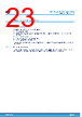
23 / 48 page  7 Power-up and delivery state 7.1 Power-up state After power-up, the device is in the following state: • Standby power mode • deselected (after power-up, a falling edge is required on Chip select (S) before any instructions can be started) • not in the Hold condition • the Write enable latch (WEL) is reset to 0 • Write in progress (WIP) is reset to 0. The SRWD, BP1 and BP0 bits of the Status register are unchanged from the previous power-down (they are non- volatile bits). 7.2 Initial delivery state The device is delivered with the memory array and Identification page bits set to all 1s (each byte = FFh). The Status register Write Disable (SRWD) and Block protect (BP1 and BP0) bits are initialized to 0. M95128-W M95128-R M95128-DF Power-up and delivery state DS1356 - Rev 20 page 23/48 |
|
Link URL |
| Does ALLDATASHEET help your business so far? [ DONATE ] |
About Alldatasheet | Advertisement | Contact us | Privacy Policy | Link to Datasheet | Link Exchange | Manufacturer List All Rights Reserved©Alldatasheet.com |
| Russian : Alldatasheetru.com | Korean : Alldatasheet.co.kr | Spanish : Alldatasheet.es | French : Alldatasheet.fr | Italian : Alldatasheetit.com Portuguese : Alldatasheetpt.com | Polish : Alldatasheet.pl | Vietnamese : Alldatasheet.vn Indian : Alldatasheet.in | Mexican : Alldatasheet.com.mx | British : Alldatasheet.co.uk | New Zealand : Alldatasheet.co.nz |
|
Family Site : ic2ic.com |
icmetro.com |
 New Zealand ▼
 English
 Chinese
 German
 Japanese
 Russian
 Korean
 Spanish
 French
 Italian
 Portuguese
 Polish
 Vietnamese
 Indian
 Mexican
 British
 New Zealand