 |
Electronic Components Datasheet Search |
|
|
Electronic Components Datasheet Search |
|
LX2160A-RDB-B Datasheet(PDF) 33 Page - NXP Semiconductors |
|
|
|||||||||||||||||||||||||||||
LX2160A-RDB-B Datasheet(HTML) 33 Page - NXP Semiconductors |
|
|
33 / 116 page 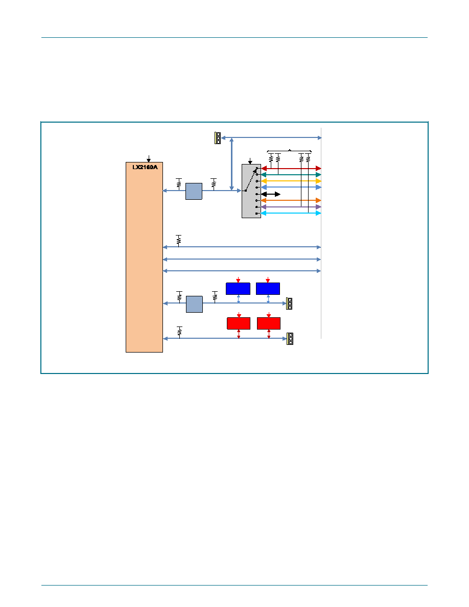 2.10 I2C interface The LX2160A processor supports up to six I2C buses. Most system devices (other than UEFI) are accessed via I2C1 port, which is connected to a PCA9547PW I2C multiplexer to isolate address conflicts and effectively manage the large number of I2C devices. The I2C1 port is translated to 3V3_SB to provide programming access to power controllers, clocks, memories, and so on, when the system is powered off. The figure below shows the I2C bus architecture. I2C6 I2C3 I2C2 I2C1 Remote Access I2C1 Addr = 0x77 PCA9547PW 3V3_SB I2C1_CH0 I2C1_CH7 0 1 2 3 4 5 6 7 0 1 2 3 4 5 6 7 OVDD OVDD OVDD (1.8V) SDHC1_CD_B SDHC1_WP I2C1_CH1 I2C1_CH2 I2C1_CH3 I2C1_CH5 I2C1_CH6 3V3_SB (all 8 channels) ... unused Volt Trans 3V3_SB 3V3_SB CPLD OVDD OVDD CAN1_RX CAN1_TX I2C4 CAN2_RX CAN2_TX I2C5 I2C6 Remote Access OVDD OVDD Volt Trans 3V3_SB 3V3_SB Real-Time Clock PCF2129 Addr 0x51 3V3_SB 3V3_SB UEFI Mem AT24CM02 Addr 0x54-0x57 3V3_SB 3V3_SB I2C5 Remote Access AQR107 #1 AQR107 #2 Addr SW Addr SW OVDD OVDD 1V8 1V8 1V8 1V8 Figure 20. I2C bus architecture The multiplexer used for the I2C1 bus partitions the bus into eight sub-buses, called "channels." Software must program the multiplexer to access one of the eight I2C1 channels. All boot-software-dependent devices are placed on channel 0, or "I2C1_CH0" as it is named. Channel 0 is the default selection upon reset so that software has immediate access to critical resources. The I2C devices indirectly available on the I2C1 bus are shown in the figure below. NXP Semiconductors LX2160ARDB Functional Description QorIQ LX2160A Reference Design Board Reference Manual, Rev. 4, 07/2020 Reference Manual 33 / 116 |
|
Link URL |
| Does ALLDATASHEET help your business so far? [ DONATE ] |
About Alldatasheet | Advertisement | Contact us | Privacy Policy | Link to Datasheet | Link Exchange | Manufacturer List All Rights Reserved©Alldatasheet.com |
| Russian : Alldatasheetru.com | Korean : Alldatasheet.co.kr | Spanish : Alldatasheet.es | French : Alldatasheet.fr | Italian : Alldatasheetit.com Portuguese : Alldatasheetpt.com | Polish : Alldatasheet.pl | Vietnamese : Alldatasheet.vn Indian : Alldatasheet.in | Mexican : Alldatasheet.com.mx | British : Alldatasheet.co.uk | New Zealand : Alldatasheet.co.nz |
|
Family Site : ic2ic.com |
icmetro.com |
 New Zealand ▼
 English
 Chinese
 German
 Japanese
 Russian
 Korean
 Spanish
 French
 Italian
 Portuguese
 Polish
 Vietnamese
 Indian
 Mexican
 British
 New Zealand


