|
Electronic Components Datasheet Search |
|
|
Electronic Components Datasheet Search |
|
MAX4586 Datasheet(PDF) 8 Page - Maxim Integrated Products |
|
|
|||||||||||||||||||||||||||||
MAX4586 Datasheet(HTML) 8 Page - Maxim Integrated Products |
|
|
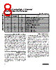
8 / 12 page  Detailed Description The MAX4586/MAX4587 are serial-interface, programma- ble multiplexers. Each device contains a 4-to-1 normally open (NO) multiplexer. Each switch is independently con- trolled through the on-chip serial interface. The MAX4586 uses a 2-wire, I2C-compatible serial communications protocol, and the MAX4587 uses a 3-wire, SPI/QSPI/ MICROWIRE-compatible serial communications protocol. These devices operate from a single +2.7V to +5.5V supply and are optimized for use with an audio fre- quency at 20kHz and video frequencies up to 10MHz. They feature 65 Ω on-resistance, 4Ω on-resistance matching between channels, and 5 Ω on-resistance flat- ness. Audio off-isolation is -83dB at 20kHz and crosstalk is at least -84dB at 20kHz, while video off-iso- lation is -48dB at 10MHz and crosstalk is at least -60dB at 10MHz. Applications Information Multiplexer Control The MAX4586/MAX4587 have a common command-bit structure; the only difference between them is the inter- face type (2-wire or 3-wire, respectively). The command controls the open/closed states of the various switches. Table 1 shows the configuration of the data bits and their related switches. After a com- mand is issued, a logic “1” in any data-bit location clos- es the associated switch, while a logic “0” opens it (Table 2). 2-Wire Serial Interface The MAX4586 uses a 2-wire, I2C-compatible serial interface. The COM_ register uses the “SendByte” pro- tocol that consists of an address byte followed by a command byte (Table 1). To address a given chip, the A bit in the address byte must duplicate the value present at the A pin of that chip. The rest of the address bits must match those shown in Table 3. The command byte details are described in the Switch Control section. The 2-wire serial interface requires only two I/O lines of a standard microprocessor (µP) port. Figures 1 and 2 detail the timing diagram for signals on the 2-wire bus, and Tables 1 and 3 detail the format of the signals. The MAX4586 is a receive-only device and must be con- trolled by the bus master device. A bus master device communicates by transmitting the address byte of the slave device over the bus and then transmitting the desired information. Each transmission consists of a start condition, an address byte, a command byte, and finally a stop condition. The slave device acknowledges the recognition of its address by pulling the SDA line low for one clock period after the address byte is trans- mitted. The slave device also issues a similar acknowl- edgment after the command byte. Serially Controlled, 4-Channel Audio/Video Multiplexers 8 _______________________________________________________________________________________ Pin Description 9 8 9 7 7 — 5 4 4 8 6 — 3 — 2 — 1 NO3 NO2 6 SCLK 5 V+ COM 1 SDA GND NO1 SCL DIN 3 — CS — A 2 Mux Normally Open Output 3 Mux Normally Open Output 2 Clock Input of the 3-Wire Serial Interface Supply Voltage Analog Switch Common Terminal Data Input of 2-Wire Serial Interface Ground Mux Normally Open Output 1 Clock Input of the 2-Wire Serial Interface Data Input of 3-Wire Serial Interface Chip Select of the 3-Wire Serial Interface LSB + 2 of the 2-Wire Serial-Interface Address Field 10 10 NO4 Mux Normally Open Output 4 MAX4587 MAX4586 PIN NAME FUNCTION |
|
|
Link URL |
| Does ALLDATASHEET help your business so far? [ DONATE ] |
About Alldatasheet | Advertisement | Contact us | Privacy Policy | Link to Datasheet | Link Exchange | Manufacturer List All Rights Reserved©Alldatasheet.com |
| Russian : Alldatasheetru.com | Korean : Alldatasheet.co.kr | Spanish : Alldatasheet.es | French : Alldatasheet.fr | Italian : Alldatasheetit.com Portuguese : Alldatasheetpt.com | Polish : Alldatasheet.pl | Vietnamese : Alldatasheet.vn Indian : Alldatasheet.in | Mexican : Alldatasheet.com.mx | British : Alldatasheet.co.uk | New Zealand : Alldatasheet.co.nz |
|
Family Site : ic2ic.com |
icmetro.com |
 New Zealand ▼
 English
 Chinese
 German
 Japanese
 Russian
 Korean
 Spanish
 French
 Italian
 Portuguese
 Polish
 Vietnamese
 Indian
 Mexican
 British
 New Zealand