|
Electronic Components Datasheet Search |
|
|
Electronic Components Datasheet Search |
|
LT6211CDD Datasheet(PDF) 16 Page - Linear Technology |
|
|
|||||||||||||||||||||||||||||
LT6211CDD Datasheet(HTML) 16 Page - Linear Technology |
|
|
16 / 16 page 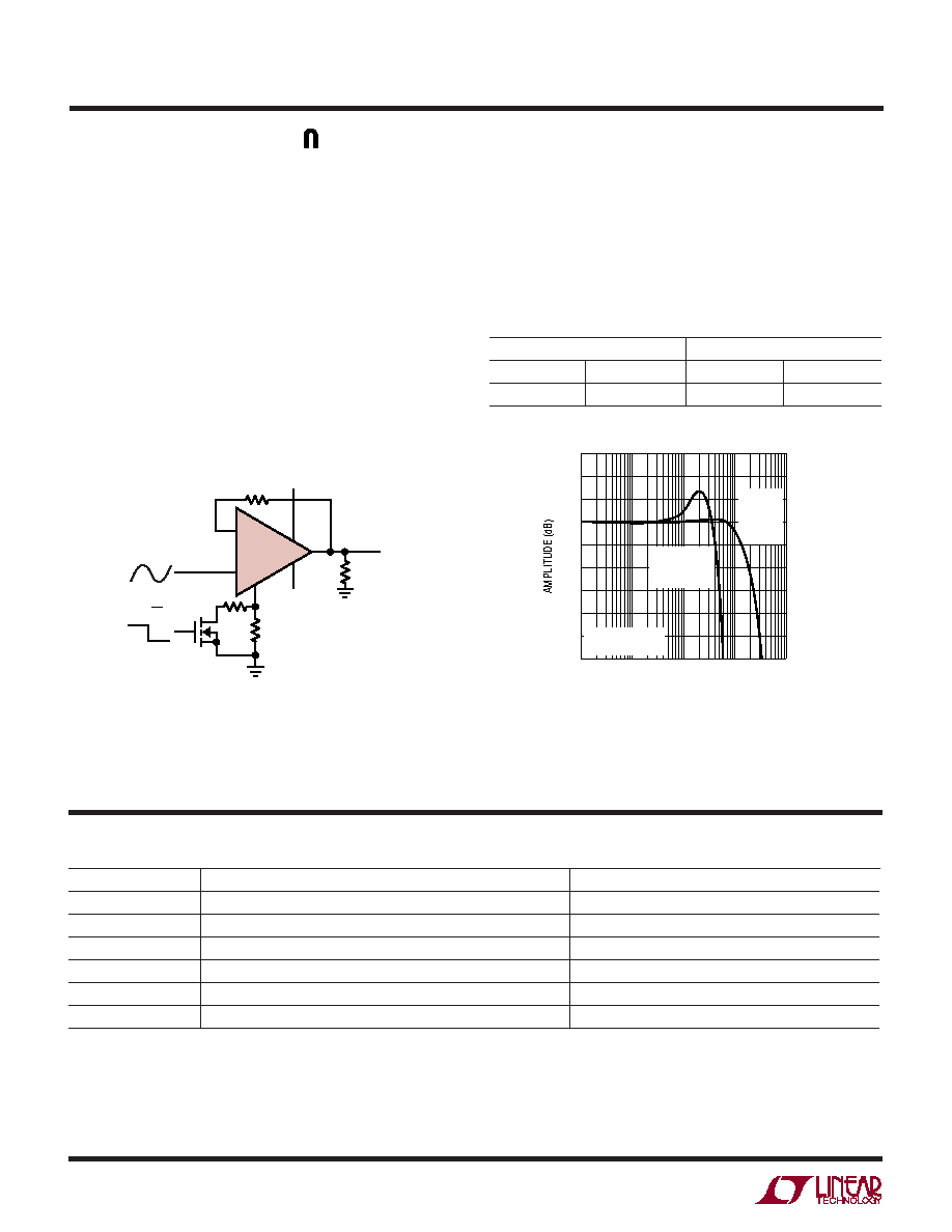 16 LT6210/LT6211 62101f LT/TP 0204 1K • PRINTED IN USA ©LINEAR TECHNOLOGY CORPORATION 2003 Linear Technology Corporation 1630 McCarthy Blvd., Milpitas, CA 95035-7417 (408) 432-1900 q FAX: (408) 434-0507 q www.linear.com RELATED PARTS PART NUMBER DESCRIPTION COMMENTS LT1252/LT1253/LT1254 100MHz Low Cost Video Amplifiers Single, Dual and Quad Current Feedback Amplifiers LT1395/LT1396/LT1397 400MHz, 800V/ µs Amplifiers Single, Dual and Quad Current Feedback Amplifiers LT1398/LT1399 300MHz Amplifiers with Shutdown Dual and Triple Current Feedback Amplifiers LT1795 50MHz, 500mA Programmable IS Amplifier Dual Current Feedback Amplifier LT1806/LT1807 325MHz, 140V/ µs Rail-to-Rail I/O Amplifiers Single and Dual Voltage Feedback Amplifiers LT1815/LT1816/LT1817 220MHz, 1500V/ µs Programmable IS Operational Amplifier Single, Dual and Quad Voltage Feedback Amplifiers TYPICAL APPLICATIO S Figure 5. Line Driver with Low Power Mode Figure 6. Frequency Response for Full Speed and Low Power Mode Line Driver with Power Saving Mode In applications where low distortion or high slew rate are desirable but not necessary at all times, it may be possible to decrease the LT6210 or LT6211’s quiescent current when the higher power performance is not required. Figure 5 illustrates a method of setting quiescent current with a FET switch. In the 5V dual supply case pictured, shorting the ISET pin through an effective 20k to ground sets the supply current to 6mA, while the 240k resistor at the ISET pin with the FET turned off sets the supply current to approximately 1mA. The feedback resistor of 4.02k is selected to minimize peaking in low power mode. The bandwidth of the LT6210 in this circuit increases from about 40MHz in low power mode to over 200MHz in full speed mode, as illustrated in Figure 6. Other AC specs also improve significantly at the higher current setting. The following table shows harmonic distortion at 1MHz with a 2VP-P sinusoid at the two selected current levels. Harmonic Distortion LOW POWER FULL SPEED HD2 –53dBc HD2 –68dBc HD3 –46dBc HD3 –77dBc FREQUENCY (MHz) –4 –2 –1 1 3 0 10 100 1000 6210 F06 –6 1 0 –3 –5 2 FULL SPEED MODE IS = 6mA LOW POWER MODE IS = 1mA TA = 25°C VOUT = 100mVP-P – + LT6210 R1 240k R2 22k RLOAD 150 Ω VOUT 6210 F05 –5V R3 4.02k HS/LP VIN 5V 4 5 2 6 1 3 2N7002 |
|
|
Link URL |
| Does ALLDATASHEET help your business so far? [ DONATE ] |
About Alldatasheet | Advertisement | Contact us | Privacy Policy | Link to Datasheet | Link Exchange | Manufacturer List All Rights Reserved©Alldatasheet.com |
| Russian : Alldatasheetru.com | Korean : Alldatasheet.co.kr | Spanish : Alldatasheet.es | French : Alldatasheet.fr | Italian : Alldatasheetit.com Portuguese : Alldatasheetpt.com | Polish : Alldatasheet.pl | Vietnamese : Alldatasheet.vn Indian : Alldatasheet.in | Mexican : Alldatasheet.com.mx | British : Alldatasheet.co.uk | New Zealand : Alldatasheet.co.nz |
|
Family Site : ic2ic.com |
icmetro.com |
 New Zealand ▼
 English
 Chinese
 German
 Japanese
 Russian
 Korean
 Spanish
 French
 Italian
 Portuguese
 Polish
 Vietnamese
 Indian
 Mexican
 British
 New Zealand