 |
Electronic Components Datasheet Search |
|
|
Electronic Components Datasheet Search |
|
R8-NM1-R Datasheet(PDF) 6 Page - M-System Co.,Ltd. |
|
|
|||||||||||||||||||||||||||||
R8-NM1-R Datasheet(HTML) 6 Page - M-System Co.,Ltd. |
|
|
6 / 10 page 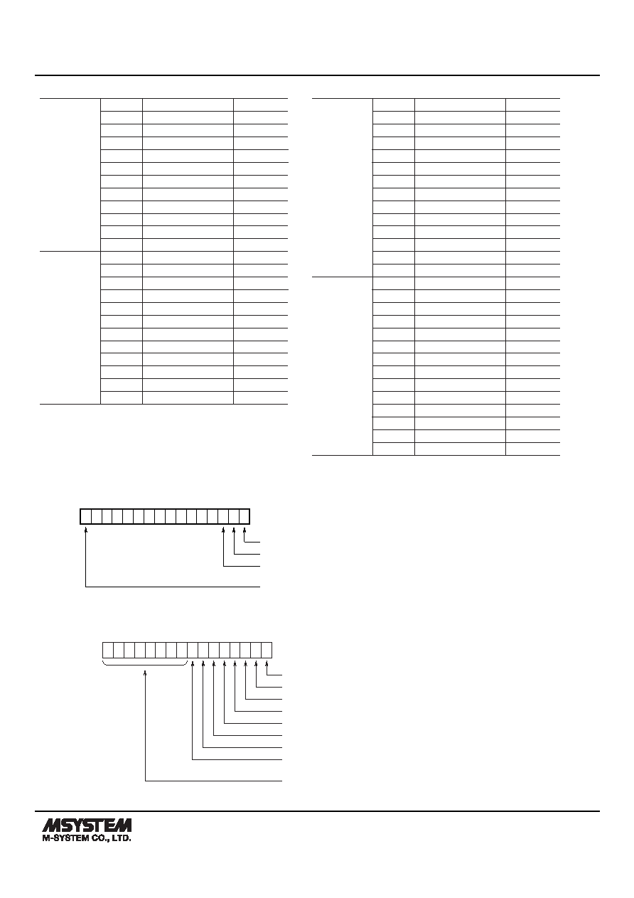 MODEL: R8-NM1 R8-NM1 SPECIFICATIONS ES-9722 Rev.5 Page 6/10 http://www.m-system.co.jp/ ■ Data Allocation Mode 1 Input Registers (3X) 1 Module address 0 Ai 1 (INT) 2 Module address 1 Ai 1 (INT) 3 Module address 2 Ai 1 (INT) 4 Module address 3 Ai 1 (INT) : : : 32 Module address 31 Ai 1 (INT) 33, 34 Module address 0 Ai 1 (Float) 35, 36 Module address 1 Ai 1 (Float) 37, 38 Module address 2 Ai 1 (Float) 39, 40 Module address 3 Ai 1 (Float) : : : 95, 96 Module address 31 Ai 1 (Float) Holding Registers (4X) 1 Module address 0 Ao 1 (INT) 2 Module address 1 Ao 1 (INT) 3 Module address 2 Ao 1 (INT) 4 Module address 3 Ao 1 (INT) : : : 32 Module address 31 Ao 1 (INT) 33, 34 Module address 0 Ao 1 (Float) 35, 36 Module address 1 Ao 1 (Float) 37, 38 Module address 2 Ao 1 (Float) 39, 40 Module address 3 Ao 1 (Float) : : : 95, 96 Module address 31 Ao 1 (Float) ■ Data Allocation Mode 2 Input Registers (3X) 1 Module address 0 Ai 1 (INT) 2 Module address 0 Ai 2 (INT) 3 Module address 1 Ai 1 (INT) 4 Module address 1 Ai 2 (INT) : : : 63 Module address 31 Ai 1 (INT) 64 Module address 31 Ai 2 (INT) 65, 66 Module address 0 Ai 1 (Float) 67, 68 Module address 0 Ai 2 (Float) 69, 70 Module address 1 Ai 1 (Float) 71, 72 Module address 1 Ai 2 (Float) : : : 189, 190 Module address 31 Ai 1 (Float) 191, 192 Module address 31 Ai 2 (Float) Holding Registers (4X) 1 Module address 0 Ao 1 (INT) 2 Module address 0 Ao 2 (INT) 3 Module address 1 Ao 1 (INT) 4 Module address 1 Ao 2 (INT) : : : 63 Module address 31 Ao 1 (INT) 64 Module address 31 Ao 2 (INT) 65, 66 Module address 0 Ao 1 (Float) 67, 68 Module address 0 Ao 2 (Float) 69, 70 Module address 1 Ao 1 (Float) 71, 72 Module address 1 Ao 2 (Float) : : : 189, 190 Module address 31 Ao 1 (Float) 191, 192 Module address 31 Ao 2 (Float) 513 544 ■ ACTIVE MODULE MAP Indicates the I/O modules are mounted to the board. When the module is mounted, the corresponding bit turns to “1.” Module address 0 Module address 1 Module address 2 Module address 31 ■ STATUS Communication status data. When one or more I/O modules are mounted on the base, the corresponding bit turns to “0.” 545 560 “0” “0” “0” “0” I/O Module Found (0 : I/O module(s) found, 1 : No I/O module found) “0” “0” “0” Internal Communication Counter (Every Internal Communication Cycle Adds +1) |
|
|
Link URL |
| Does ALLDATASHEET help your business so far? [ DONATE ] |
About Alldatasheet | Advertisement | Contact us | Privacy Policy | Link to Datasheet | Link Exchange | Manufacturer List All Rights Reserved©Alldatasheet.com |
| Russian : Alldatasheetru.com | Korean : Alldatasheet.co.kr | Spanish : Alldatasheet.es | French : Alldatasheet.fr | Italian : Alldatasheetit.com Portuguese : Alldatasheetpt.com | Polish : Alldatasheet.pl | Vietnamese : Alldatasheet.vn Indian : Alldatasheet.in | Mexican : Alldatasheet.com.mx | British : Alldatasheet.co.uk | New Zealand : Alldatasheet.co.nz |
|
Family Site : ic2ic.com |
icmetro.com |
 New Zealand ▼
 English
 Chinese
 German
 Japanese
 Russian
 Korean
 Spanish
 French
 Italian
 Portuguese
 Polish
 Vietnamese
 Indian
 Mexican
 British
 New Zealand


