|
Electronic Components Datasheet Search |
|
|
Electronic Components Datasheet Search |
|
CC400-RTR2 Datasheet(PDF) 11 Page - Texas Instruments |
|
|
|
|||||||||||||||||||||||||||||
CC400-RTR2 Datasheet(HTML) 11 Page - Texas Instruments |
|
|
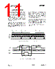
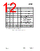
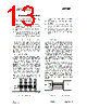
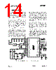
11 / 31 page 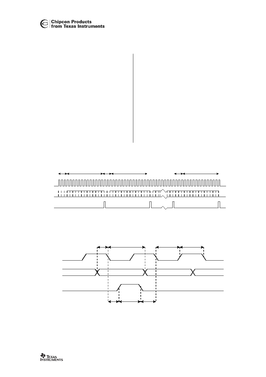 CC400 SWRS050 Page 11 of 32 14. 3-wire Serial Interface CC400 is programmed via a simple 3-wire interface (STROBE, PDATA and CLOCK). A full configuration of CC400 requires sending 8 data frames of 16 bits each. With a clock rate of 2 MHz the time needed for a full configuration will therefore be less than 100 µs. Setting the device in power down mode requires sending one frame only and will therefore take less than 10 µs. In each write-cycle 16 bits are sent on the PDATA-line. The three most significant bits of each data frame (bit15, bit14 and bit13) are the address-bits. Bit15 is the MSB of the address and is sent as the first bit. See Figure 4. A timing diagram for the programming is shown in Figure 5. The clocking of the data on PDATA is done on the negative edge of CLOCK. When the last bit, bit0, of the sixteen bits has been loaded, the STROBE-pulse must be brought high and then low to load the data. The configuration data will be valid after a programmed power-down mode, but not when the power-supply is turned off. When changing mode, only the frames that are different need to be programmed. The timing specifications are given in Table 10. CLOCK PDATA STROBE 000 00 1 11 1 01 1 Address first frame (000) Data first frame Address last frame (111) Data last frame Address second frame (001) Data second frame M S B L S B L S B L S B M S B M S B L S B Figure 4: Serial data transfer (full configuration). CLOCK STROBE PDATA BIT 0 BIT 1 BIT 15 BIT 14 TSD THD TCS TSC TS,min TCL,min TCH,min Figure 5: Timing diagram, serial interface. |
|
Link URL |
| Does ALLDATASHEET help your business so far? [ DONATE ] |
About Alldatasheet | Advertisement | Contact us | Privacy Policy | Link to Datasheet | Link Exchange | Manufacturer List All Rights Reserved©Alldatasheet.com |
| Russian : Alldatasheetru.com | Korean : Alldatasheet.co.kr | Spanish : Alldatasheet.es | French : Alldatasheet.fr | Italian : Alldatasheetit.com Portuguese : Alldatasheetpt.com | Polish : Alldatasheet.pl | Vietnamese : Alldatasheet.vn Indian : Alldatasheet.in | Mexican : Alldatasheet.com.mx | British : Alldatasheet.co.uk | New Zealand : Alldatasheet.co.nz |
|
Family Site : ic2ic.com |
icmetro.com |
 New Zealand ▼
 English
 Chinese
 German
 Japanese
 Russian
 Korean
 Spanish
 French
 Italian
 Portuguese
 Polish
 Vietnamese
 Indian
 Mexican
 British
 New Zealand