|
Electronic Components Datasheet Search |
|
|
Electronic Components Datasheet Search |
|
CC400-RTR2 Datasheet(PDF) 21 Page - Texas Instruments |
|
|
|
|||||||||||||||||||||||||||||
CC400-RTR2 Datasheet(HTML) 21 Page - Texas Instruments |
|
|
21 / 31 page 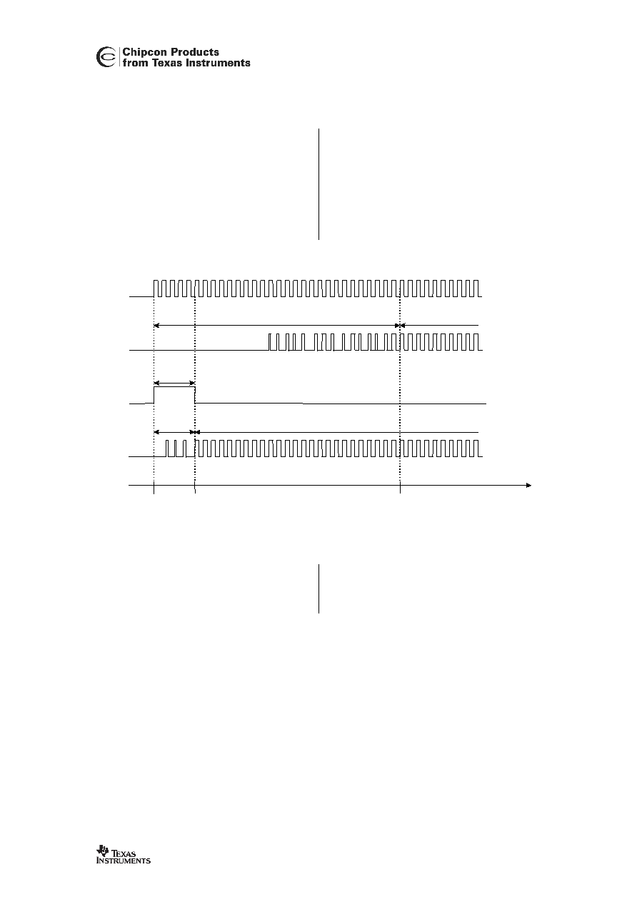 CC400 SWRS050 Page 21 of 32 27. Demodulator Precharging For Reduced Turn-on Time The demodulator data slicer has an internal AC coupling giving a time constant of approximately 30 periods of the bit rate period. This means that before proper demodulation can take place, a minimum of 30 start-bits has to be received. In critical applications where the start-up time should be decreased in order to reduce the power consumption, this time constant can be reduced to 5 periods using the optional precharging possibility. The precharging is done during data reception by setting the precharging bit in the configuration register active with duration of at least 5 bit periods. Data received without precharging PRECHARGE Time Data transmitted 5 bit periods t1 t2 t3 Data valid Data not valid Data valid Data not valid 5 bit periodes 30 bit periodes Data received with precharging Figure 12: Demodulation using precharging. In the example shown in Figure 12, data is transmitted continuously from the transmitter (all 1’s). At t=t1 the receiver is turned on, and then the precharging is kept on for about 5 bit periods. At t=t2 the received data is valid and precharging is turned off. When not using precharging, data is not valid until 30 bit periods, at t=t3. |
|
Link URL |
| Does ALLDATASHEET help your business so far? [ DONATE ] |
About Alldatasheet | Advertisement | Contact us | Privacy Policy | Link to Datasheet | Link Exchange | Manufacturer List All Rights Reserved©Alldatasheet.com |
| Russian : Alldatasheetru.com | Korean : Alldatasheet.co.kr | Spanish : Alldatasheet.es | French : Alldatasheet.fr | Italian : Alldatasheetit.com Portuguese : Alldatasheetpt.com | Polish : Alldatasheet.pl | Vietnamese : Alldatasheet.vn Indian : Alldatasheet.in | Mexican : Alldatasheet.com.mx | British : Alldatasheet.co.uk | New Zealand : Alldatasheet.co.nz |
|
Family Site : ic2ic.com |
icmetro.com |
 New Zealand ▼
 English
 Chinese
 German
 Japanese
 Russian
 Korean
 Spanish
 French
 Italian
 Portuguese
 Polish
 Vietnamese
 Indian
 Mexican
 British
 New Zealand