|
Electronic Components Datasheet Search |
|
|
Electronic Components Datasheet Search |
|
DCS-7304XFM-R Datasheet(PDF) 19 Page - Arista Networks, Inc |
|
|
|||||||||||||||||||||||||||||
DCS-7304XFM-R Datasheet(HTML) 19 Page - Arista Networks, Inc |
|
|
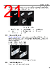
19 / 66 page  Rack Mounting the Switch 3.2 Four-Post Rack Mount The switch is mounted onto a four-post rack by assembling a shelf into the rack, then attaching the switch on the shelf. The four-post rack mount instructions include these sections: • Component Description • Component Placement • Switch Mounting Process 3.2.1 Component Description The four-post mount accessory kit contains these components: • 1 Left Shelf and 1 Right Shelf (Shelves) • 2 Mounting Ears (Mounting Ears) Note: Components are designed for tool-less installation in square-hole racks. To install the switch in round hole or threaded hole racks, remove all rack plugs from rail kit, if required (described below), and attach all components with nuts and bolts that fit the rack. The finished assembly for rack mounting the device is shown in Figure 6: Left Shelf – Inner View. Detailed mounting instructions for all rack types start from Shelf Installation. Figure 5: Switch Shelves Installed Note: The parts list for rack kit installations for round and threaded hole racks are listed in Parts List. 3.2.1.1 Shelves The two shelves are almost identical, differing in that 1) they are mirror-images of each other, and 2) the left shelf includes a stabilizer bar. Each shelf is a two-piece mechanism. The base includes the surface upon which the switch is placed and is oriented towards the front of the rack. The slide-end adjusts the shelf’s length for fitting the shelf between front and rear posts of various size racks. 15 |
|
Link URL |
| Does ALLDATASHEET help your business so far? [ DONATE ] |
About Alldatasheet | Advertisement | Contact us | Privacy Policy | Link to Datasheet | Link Exchange | Manufacturer List All Rights Reserved©Alldatasheet.com |
| Russian : Alldatasheetru.com | Korean : Alldatasheet.co.kr | Spanish : Alldatasheet.es | French : Alldatasheet.fr | Italian : Alldatasheetit.com Portuguese : Alldatasheetpt.com | Polish : Alldatasheet.pl | Vietnamese : Alldatasheet.vn Indian : Alldatasheet.in | Mexican : Alldatasheet.com.mx | British : Alldatasheet.co.uk | New Zealand : Alldatasheet.co.nz |
|
Family Site : ic2ic.com |
icmetro.com |
 New Zealand ▼
 English
 Chinese
 German
 Japanese
 Russian
 Korean
 Spanish
 French
 Italian
 Portuguese
 Polish
 Vietnamese
 Indian
 Mexican
 British
 New Zealand