|
Electronic Components Datasheet Search |
|
|
Electronic Components Datasheet Search |
|
ADRF5420BCDZ-R7 Datasheet(PDF) 5 Page - Analog Devices |
|
|
|||||||||||||||||||||||||||||
ADRF5420BCDZ-R7 Datasheet(HTML) 5 Page - Analog Devices |
|
|
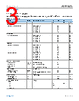
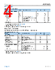
5 / 14 page 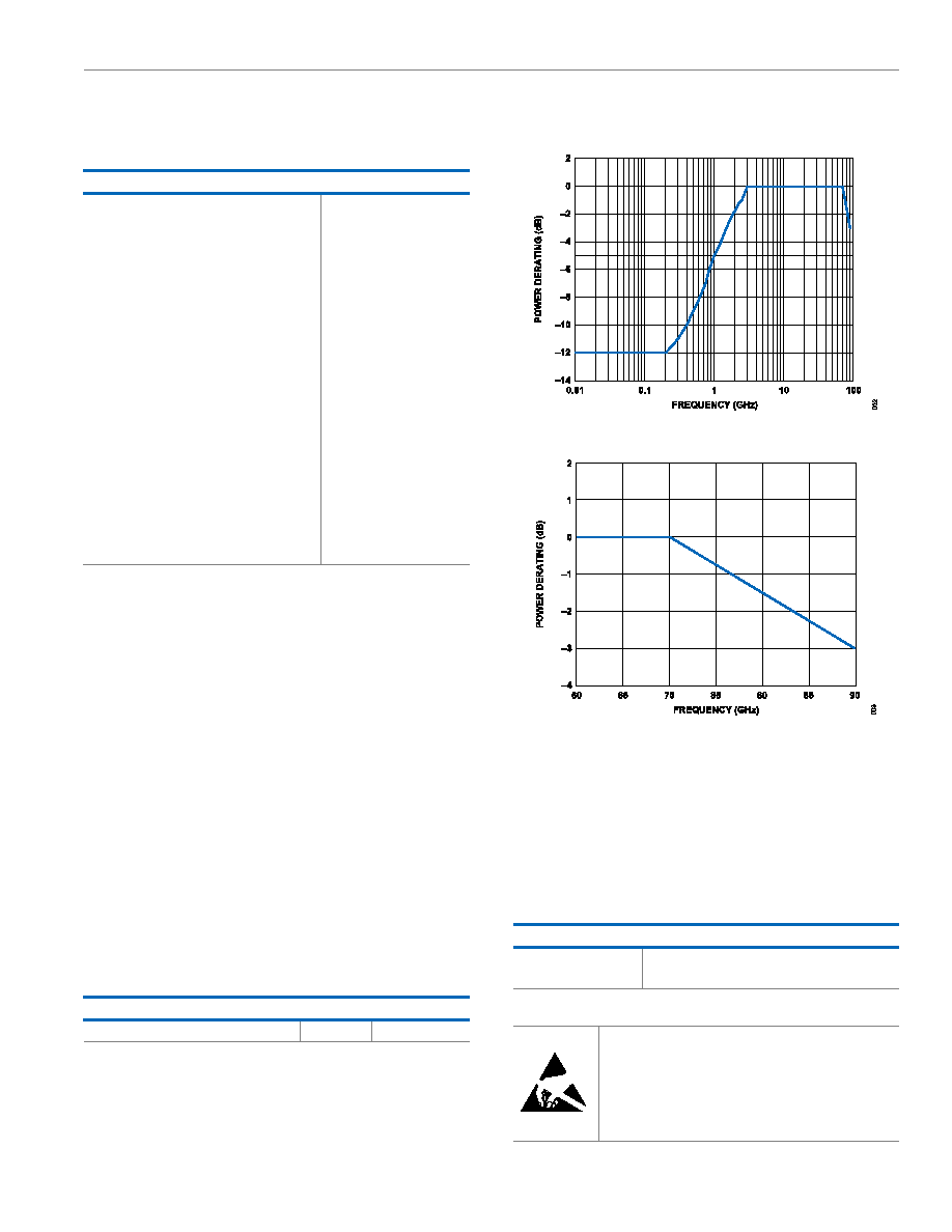 Data Sheet ADRF5420 ABSOLUTE MAXIMUM RATINGS analog.com Rev. 0 | 5 of 14 For the recommended operating conditions, see Table 1. Table 3. Absolute Maximum Ratings Parameter Rating Positive Supply Voltage −0.3V to +3.6V Negative Supply Voltage −3.6V to +0.3V Digital Control Input1 Voltage −0.3V to VDD + 0.3V Current 3mA RF Input Power, Dual Supply2 (VDD = +3.3V, VSS = −3.3V, f = 3GHz to 70GHz, TCASE = 85°C3) Through Path 25dBm Hot Switching 22dBm RF Input Power, Single Supply (VDD = 3.3V, VSS = 0V, f = 3GHz to 70GHz, TCASE = 85°C3) Through Path 15dBm Hot Switching (RFC) 12dBm RF Input Power Under Unbiased Condition (VDD and VSS = 0V) 15dBm Temperature Junction, TJ 135°C Storage Range −65°C to +150°C Reflow 260°C 1 Overvoltages at the digital control input are clamped by internal diodes. Current must be limited to the maximum rating given. 2 For power derating over frequency, see Figure 2 and Figure 3. 3 For 105°C operation, the power handling degrades from the TCASE = 85°C specification by 3 dB for dual supply and 1dB for single supply. Stresses at or above those listed under Absolute Maximum Ratings may cause permanent damage to the product. This is a stress rating only; functional operation of the product at these or any other conditions above those indicated in the operational section of this specification is not implied. Operation beyond the maximum operat- ing conditions for extended periods may affect product reliability. Only one absolute maximum rating can be applied at any one time. THERMAL RESISTANCE Thermal performance is directly linked to printed circuit board (PCB) design and operating environment. Careful attention to PCB thermal design is required. θJC is the junction to case bottom (channel to package bottom) thermal resistance. Table 4. Thermal Resistance Package Type θJC1 Unit CD-30-3, Through Path 537 °C/W 1 θJC was determined by simulation under the following conditions: the heat transfer is due solely to the thermal conduction from the channel through the ground pad to the PCB, and the ground pad is held constant at the operating temperature of 85°C. POWER DERATING CURVES Figure 2. Power Derating vs. Frequency, Low Frequency Detail, TCASE = 85°C Figure 3. Power Derating vs. Frequency, High Frequency Detail, TCASE = 85°C ELECTROSTATIC DISCHARGE (ESD) RATINGS The following ESD information is provided for handling of ESD-sen- sitive devices in an ESD-protected area only. Human body model (HBM) per ANSI/ESDA/JEDEC JS-001. ESD Ratings for the ADRF5420 Table 5. ADRF5420, 30-Ball BUMPED_CHIP ESD Model Withstand Threshold (V) HBM ±500 for the RF pins ±2000 for the supply and digital control pins ESD CAUTION ESD (electrostatic discharge) sensitive device. Charged devices and circuit boards can discharge without detection. Although this product features patented or proprietary protec- tion circuitry, damage may occur on devices subjected to high energy ESD. Therefore, proper ESD precautions should be taken to avoid performance degradation or loss of functionality. |
|
|
Link URL |
| Does ALLDATASHEET help your business so far? [ DONATE ] |
About Alldatasheet | Advertisement | Contact us | Privacy Policy | Link to Datasheet | Link Exchange | Manufacturer List All Rights Reserved©Alldatasheet.com |
| Russian : Alldatasheetru.com | Korean : Alldatasheet.co.kr | Spanish : Alldatasheet.es | French : Alldatasheet.fr | Italian : Alldatasheetit.com Portuguese : Alldatasheetpt.com | Polish : Alldatasheet.pl | Vietnamese : Alldatasheet.vn Indian : Alldatasheet.in | Mexican : Alldatasheet.com.mx | British : Alldatasheet.co.uk | New Zealand : Alldatasheet.co.nz |
|
Family Site : ic2ic.com |
icmetro.com |
 New Zealand ▼
 English
 Chinese
 German
 Japanese
 Russian
 Korean
 Spanish
 French
 Italian
 Portuguese
 Polish
 Vietnamese
 Indian
 Mexican
 British
 New Zealand