|
Electronic Components Datasheet Search |
|
|
Electronic Components Datasheet Search |
|
SFM3000 Datasheet(PDF) 5 Page - List of Unclassifed Manufacturers |
|
|
|||||||||||||||||||||||||||||
SFM3000 Datasheet(HTML) 5 Page - List of Unclassifed Manufacturers |
|
|
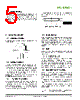
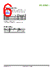
5 / 7 page  www.sensirion.com Version 2 – February 2014 5/7 3.4 Mechanical fitting Fittings of the SFM3000 sensor correspond to the international standard ISO5356-1:2004. Details about this type of connection can be found in the description of the standard. To minimize the risk of connectors being accidentally disconnected, latching connectors can be suggested. It is also possible to insert O-rings in the grooves and attach tubes with an inner diameter of 23 mm to the SFM3000. Cross section of recommended O-ring 4. Instructions for Use 4.1 Calibration orientation The sensors are calibrated horizontally as depicted in the following graph: 4.2 Inlet flow conditions In order to provide good flow conditions, the inner diameter of the connecting tube has to be approximately the same as the inner diameter of the SFM3000 main flow channel. The inlet tube has to be straight and at least 10 cm in length. The SFM3000 is equipped with meshes on the in- and outlets of the flow channel to reduce turbulences and thus improve the stability. Please refer to the application note “Inlet conditions for the SFM3000 Mass flow meters” for more information. 4.3 Temperature compensation The SFM3000 sensor features digital temperature compensation. The temperature is measured on the CMOSens® chip by an on-chip temperature sensor. This data is fed to a compensation circuit that is also integrated on the CMOSens® sensor chip. Thus, no external temperature compensation is necessary. 4.4 Sensor handling The SFM3000 sensor is designed to be robust and shock resistant. Nevertheless, the accuracy of the high-precision SFM3000 can be degraded by rough handling. Sensirion does not guarantee proper operation in case of improper handling. Note: avoid applying any mechanical stress to the solder joints of the sensor during or as a result of PCB assembly. 4.5 ESD The electronics of the SFM3000 sensor consist of a single automotive qualified chip. It complies with the following ESD norms: - AEC Q 100 002 (4kV HBM) - AEC Q 100 003 (200V MM) Although the sensor complies with these norms, it does not mean the sensor is immune against ESD. The sensor is shipped in an antistatic tray to prevent electrostatic discharge. To avoid damage to the sensor, ground yourself using a grounding strap or by touching a grounded object before touching the sensor. Furthermore, store the parts in an antistatic package when not in use. 4.6 I2C Interface and communication Due to I2C interface restrictions, the cable length from the sensor to the microprocessor is recommended to be as short as possible and certainly not above 30 cm. For wires longer than 10 cm it is mandatory to shield the SDA and SCL. In case data is read from the sensor, the first data byte of the transaction must always be acknowledged by the master. It must be possible to reset the sensor through a hard reset, i.e. powering off and on the sensor, in case the sensor freezes. I2C Communication details are given in the application note “I2C Functional Description for SFM3000”. d1 = 19mm d2 = 2mm |
|
|
Link URL |
| Does ALLDATASHEET help your business so far? [ DONATE ] |
About Alldatasheet | Advertisement | Contact us | Privacy Policy | Link to Datasheet | Link Exchange | Manufacturer List All Rights Reserved©Alldatasheet.com |
| Russian : Alldatasheetru.com | Korean : Alldatasheet.co.kr | Spanish : Alldatasheet.es | French : Alldatasheet.fr | Italian : Alldatasheetit.com Portuguese : Alldatasheetpt.com | Polish : Alldatasheet.pl | Vietnamese : Alldatasheet.vn Indian : Alldatasheet.in | Mexican : Alldatasheet.com.mx | British : Alldatasheet.co.uk | New Zealand : Alldatasheet.co.nz |
|
Family Site : ic2ic.com |
icmetro.com |
 New Zealand ▼
 English
 Chinese
 German
 Japanese
 Russian
 Korean
 Spanish
 French
 Italian
 Portuguese
 Polish
 Vietnamese
 Indian
 Mexican
 British
 New Zealand