|
Electronic Components Datasheet Search |
|
|
Electronic Components Datasheet Search |
|
SFM4100 Datasheet(PDF) 3 Page - List of Unclassifed Manufacturers |
|
|
|||||||||||||||||||||||||||||
SFM4100 Datasheet(HTML) 3 Page - List of Unclassifed Manufacturers |
|
|
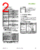
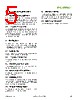
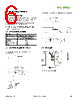
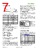
3 / 9 page  www.sensirion.com Version 1.3 – January 2013 3/9 3. Interface Specifications The serial interface of the SFM4100 series is optimized in terms of sensor readout and power consumption. It is compatible with I2C interfaces. For detailed specifications of the I2C protocol, see The I2C Bus Specification, Version 2.1, January 2000 (source: NXP). (www.nxp.com/products/interface_control/i2c) 3.1 Interface connection – external components Bi-directional bus lines are implemented by the devices (master and slave) using open-drain output stages and a pull-up resistor connected to the positive supply voltage. The recommended pull-up resistor value depends on the system setup (capacitance of the circuit or cable and bus clock frequency). In most cases, 10 kΩ is a reasonable choice. The capacitive loads on SDA and SCL line have to be the same. It is important to avoid asymmetric capacitive loads. I2C Transmission Start Condition SDA SCL VDD master slave (SDP600) Rp Rp Both bus lines, SDA and SCL, are bi-directional and therefore require an external pull-up resistor. 3.2 I2C Address The I2C address consists of a 7-digit binary value. By default, the I2C address of the SFM4100 is gas specific (see chapter 2.2). The address is always followed by a write bit (0) or read bit (1). 3.3 Transfer sequences Transmission START Condition (S): The START condi- tion is a unique situation on the bus created by the master, indicating to the slaves the beginning of a transmission sequence (the bus is considered busy after a START). I2C Transmission Start Condition S START condition SDA SCL A HIGH to LOW transition on the SDA line while SCL is HIGH Transmission STOP Condition (P): The STOP condition is a unique situation on the bus created by the master, indicating to the slaves the end of a transmission sequence (the bus is considered free after a STOP). I2C Transmission Stop Condition P STOP condition SDA SCL A LOW to HIGH transition on the SDA line while SCL is HIGH. Acknowledge (ACK) / Not Acknowledge (NACK): Each byte (8 bits) transmitted over the I2C bus is followed by an acknowledge condition from the receiver. This means that after the master pulls SCL low to complete the transmission of the 8th bit, SDA will be pulled low by the receiver during the 9th bit time. If after transmission of the 8th bit the receiver does not pull the SDA line low, this is considered to be a NACK condition. If an ACK is missing during a slave to master transmission, the slave aborts the transmission and goes into idle mode. I2C Acknowledge / Not Acknowledge ACK SCL R/_W D7 D0 ACK SDA not acknowledge acknowledge Each byte is followed by an acknowledge or a not acknowledge, generated by the receiver Handshake procedure (Hold Master): In a master-slave system, the master dictates when the slaves will receive or transmit data. However, in some situations a slave device may need time to store received data or prepare data to be transmitted. Therefore, a handshake procedure is required to allow the slave to indicate termination of internal processing. I2C Hold Master ACK SCL R/_W D7 D0 ACK SDA Hold master: SCK line pulled LOW data ready: SCK line released After the SCL pulse for the acknowledge signal, the SFM4100 series sensor (slave) can pull down the SCL line to force the master into a wait state. By releasing the SCL line, the sensor indicates that its internal processing is completed and transmission can resume. (The bold lines indicate that the sensor controls the SDA/SCL lines.) SFM4100 |
|
|
Link URL |
| Does ALLDATASHEET help your business so far? [ DONATE ] |
About Alldatasheet | Advertisement | Contact us | Privacy Policy | Link to Datasheet | Link Exchange | Manufacturer List All Rights Reserved©Alldatasheet.com |
| Russian : Alldatasheetru.com | Korean : Alldatasheet.co.kr | Spanish : Alldatasheet.es | French : Alldatasheet.fr | Italian : Alldatasheetit.com Portuguese : Alldatasheetpt.com | Polish : Alldatasheet.pl | Vietnamese : Alldatasheet.vn Indian : Alldatasheet.in | Mexican : Alldatasheet.com.mx | British : Alldatasheet.co.uk | New Zealand : Alldatasheet.co.nz |
|
Family Site : ic2ic.com |
icmetro.com |
 New Zealand ▼
 English
 Chinese
 German
 Japanese
 Russian
 Korean
 Spanish
 French
 Italian
 Portuguese
 Polish
 Vietnamese
 Indian
 Mexican
 British
 New Zealand