 |
Electronic Components Datasheet Search |
|
|
Electronic Components Datasheet Search |
|
AB08X5-RTC Datasheet(PDF) 10 Page - Abracon Corporation |
|
|
|||||||||||||||||||||||||||||
AB08X5-RTC Datasheet(HTML) 10 Page - Abracon Corporation |
|
|
10 / 33 page 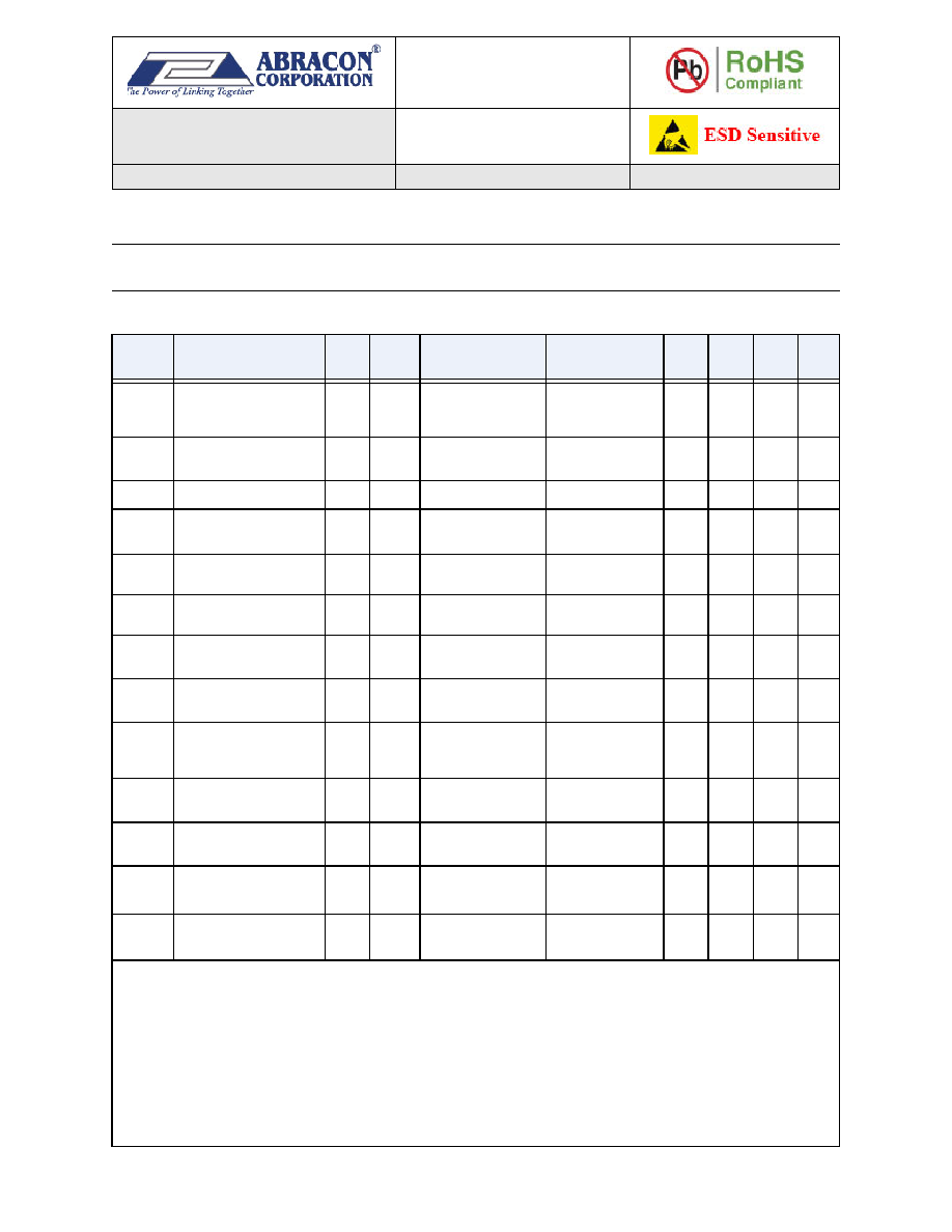 AB08X5 Real-Time Clock Family Date of Issue: October 16, 2014 3.0 x 3.0 mm Page 10 of 33 Abracon Drawing #453567 Revision: C For Table 5, T A = -40 °C to 85 °C, TYP values at 25 °C. Table 5: Power Supply and Switchover Parameters SYMBO L PARAMETER PWR TYPE POWER STATE TEST CONDITIONS MIN TYP MAX UNIT VCC System Power Voltage VCC Static VCC Power Clocks operating and RAM and registers retained 1.5 3.6 V VCCIO VCC I/O Interface Voltage VCC Static VCC Power I2C or SPI opera- tion 1.5 3.6 V VCCST VCC Start-up Voltage(1) VCC Rising POR -> VCC Power 1.6 V VCCRST VCC Reset Voltage VCC Falling VCC Power -> POR VBAT < VBAT,MIN or no VBAT 1.3 1.5 V VCCSWR VCC Rising Switch-over Threshold Voltage VCC Rising VBAT Power -> VCC Power VBAT ≥ VBATRST 1.6 1.7 V VCCSWF VCC Falling Switch-over Threshold Voltage VCC Falling VCC Power -> VBAT Power VBAT ≥ VBATSW,MIN 1.2 1.5 V VCCSWH VCC Switchover Thresh- old Hysteresis(2) VCC Hyst. VCC Power <-> VBAT Power 70 mV VCCFS VCC Falling Slew Rate to switch to VBAT state(4) VCC Falling VCC Power -> VBAT Power VCC < VCCSW,MAX 0.7 1.4 V/ms VBAT Battery Voltage VBAT Static VBAT Power Clocks operating and RAM and reg- isters retained 1.4 3.6 V VBATSW Battery Switchover Volt- age Range(5) VBAT Static VCC Power -> VBAT Power 1.6 3.6 V VBATRST Falling Battery POR Volt- age(7) VBAT Falling VBAT Power -> POR VCC < VCCSWF 1.1 1.4 V VBMRG VBAT Margin above VCC(3) VBAT Static VBAT Power 200 mV VBATESR VBAT supply series resis- tance(6) VBAT Static VBAT Power 1.0 1.5 k (1) VCC must be above VCCST to exit the POR state, independent of the VBAT voltage. (2) Difference between VCCSWR and VCCSWF. (3) VBAT must be higher than VCC by at least this voltage to ensure the AB08X5 remains in the VBAT Power state. (4) Maximum VCC falling slew rate to guarantee correct switchover to VBAT Power state. There is no VCC falling slew rate requirement if switching to the VBAT power source is not required. (5) VBAT voltage to guarantee correct transition to VBAT Power state when VCC falls. (6) Total series resistance of the power source attached to the VBAT pin. The optimal value is 1.5k, which may require an external resistor. VBAT power source ESR + external resistor value = 1.5k (7) VBATRST is also the static voltage required on VBAT for register data retention. |
|
Link URL |
| Does ALLDATASHEET help your business so far? [ DONATE ] |
About Alldatasheet | Advertisement | Contact us | Privacy Policy | Link to Datasheet | Link Exchange | Manufacturer List All Rights Reserved©Alldatasheet.com |
| Russian : Alldatasheetru.com | Korean : Alldatasheet.co.kr | Spanish : Alldatasheet.es | French : Alldatasheet.fr | Italian : Alldatasheetit.com Portuguese : Alldatasheetpt.com | Polish : Alldatasheet.pl | Vietnamese : Alldatasheet.vn Indian : Alldatasheet.in | Mexican : Alldatasheet.com.mx | British : Alldatasheet.co.uk | New Zealand : Alldatasheet.co.nz |
|
Family Site : ic2ic.com |
icmetro.com |
 New Zealand ▼
 English
 Chinese
 German
 Japanese
 Russian
 Korean
 Spanish
 French
 Italian
 Portuguese
 Polish
 Vietnamese
 Indian
 Mexican
 British
 New Zealand


