|
Electronic Components Datasheet Search |
|
|
Electronic Components Datasheet Search |
|
HMC520ALC4TR-R5 Datasheet(PDF) 26 Page - Analog Devices |
|
|
|||||||||||||||||||||||||||||
HMC520ALC4TR-R5 Datasheet(HTML) 26 Page - Analog Devices |
|
|
26 / 28 page 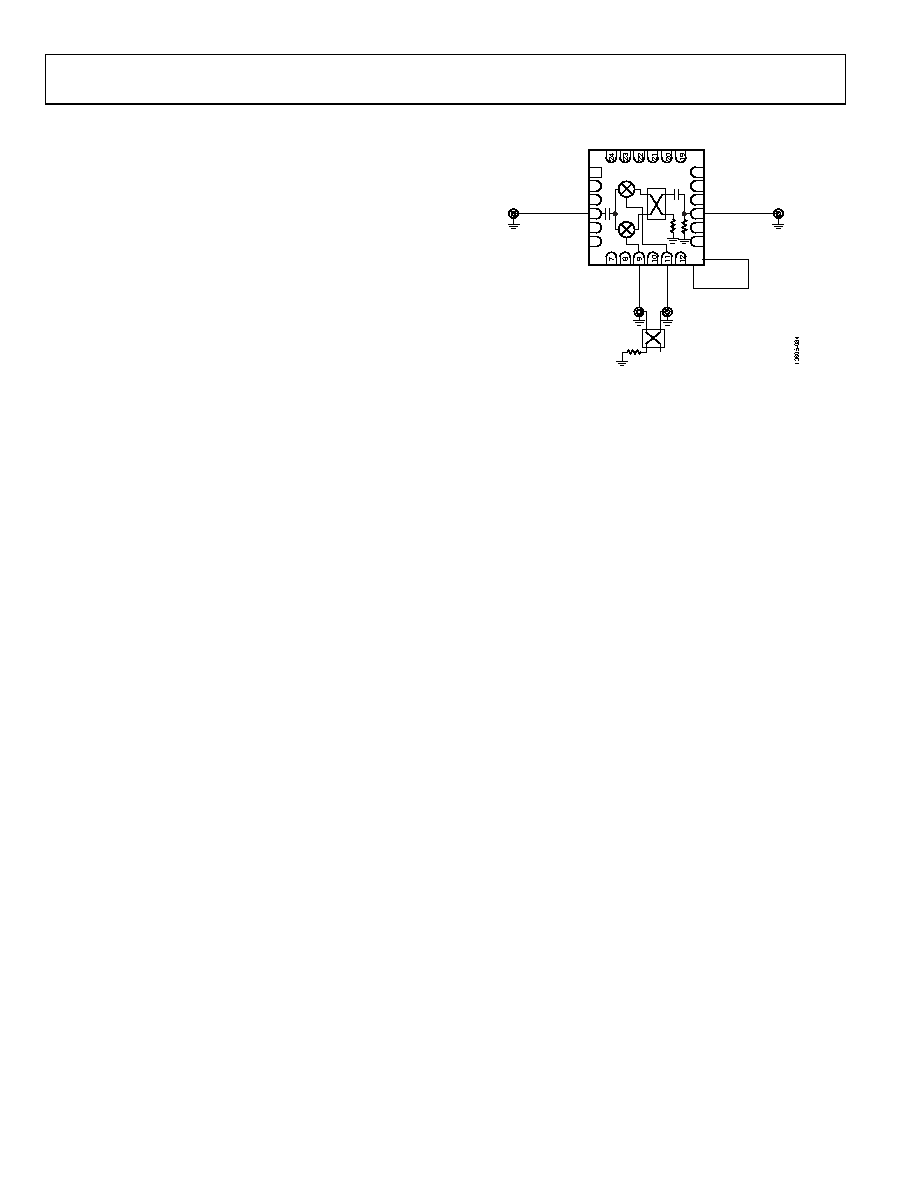 HMC520A Data Sheet Rev. 0 | Page 26 of 28 APPLICATIONS INFORMATION Figure 83 shows the typical application circuit for the HMC520A. To select the appropriate sideband, an external 90° degree hybrid is needed. For applications not requiring operation to dc, use an off-chip dc blocking capacitor. To select the upper sideband, connect IF1 to the 90° port of the hybrid and IF2 to the 0° port of the hybrid. To select the lower sideband, switch these connections. 13 1 3 4 2 5 6 14 15 16 17 18 90° HYBRID RF LO GND IF IF1 EXTERNAL 90° HYBRID IF2 PACKAGE BASE Figure 83. Typical Application Circuit |
|
Link URL |
| Does ALLDATASHEET help your business so far? [ DONATE ] |
About Alldatasheet | Advertisement | Contact us | Privacy Policy | Link to Datasheet | Link Exchange | Manufacturer List All Rights Reserved©Alldatasheet.com |
| Russian : Alldatasheetru.com | Korean : Alldatasheet.co.kr | Spanish : Alldatasheet.es | French : Alldatasheet.fr | Italian : Alldatasheetit.com Portuguese : Alldatasheetpt.com | Polish : Alldatasheet.pl | Vietnamese : Alldatasheet.vn Indian : Alldatasheet.in | Mexican : Alldatasheet.com.mx | British : Alldatasheet.co.uk | New Zealand : Alldatasheet.co.nz |
|
Family Site : ic2ic.com |
icmetro.com |
 New Zealand ▼
 English
 Chinese
 German
 Japanese
 Russian
 Korean
 Spanish
 French
 Italian
 Portuguese
 Polish
 Vietnamese
 Indian
 Mexican
 British
 New Zealand