 |
Electronic Components Datasheet Search |
|
|
Electronic Components Datasheet Search |
|
STM32F378VC Datasheet(PDF) 55 Page - STMicroelectronics |
|
|
|||||||||||||||||||||||||||||
STM32F378VC Datasheet(HTML) 55 Page - STMicroelectronics |
|
|
55 / 131 page 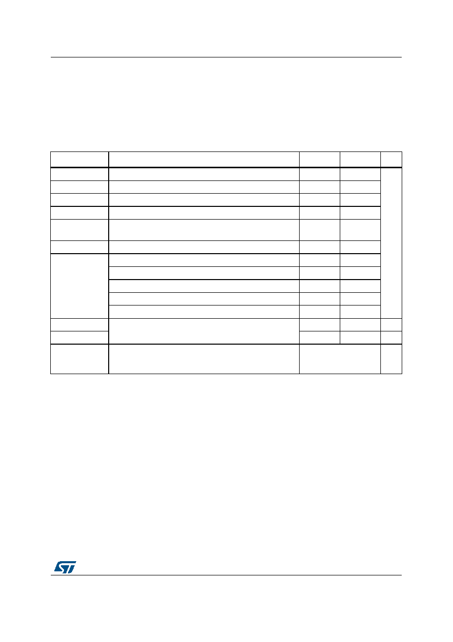 DocID025608 Rev 4 55/131 STM32F378xx Electrical characteristics 110 6.2 Absolute maximum ratings Stresses above the absolute maximum ratings listed in Table 19: Voltage characteristics, Table 20: Current characteristics, and Table 21: Thermal characteristics may cause permanent damage to the device. These are stress ratings only and functional operation of the device at these conditions is not implied. Exposure to maximum rating conditions for extended periods may affect device reliability. All main power (VDD, VDDSD12, VDDSD3 and VDDA) and ground (VSS, VSSSD, and VSSA) pins must always be connected to the external power supply, in the permitted range. The following relationship must be respected between VDDA and VDD: VDDA must power on before or at the same time as VDD in the power up sequence. VDDA must be greater than or equal to VDD. The following relationship must be respected between VDDA and VDDSD12: VDDA must power on before or at the same time as VDDSD12 or VDDSD3 in the power up sequence. VDDA must be greater than or equal to VDDSD12 or VDDSD3. Table 19. Voltage characteristics(1) Symbol Ratings Min Max Unit VDDA–VSS External main supply voltage (including VDDA, VDDSDx, VBAT) −0.3 4.0 V VDD–VSS External supply voltage VDD −0.3 1.95 VDD–VDDA Allowed voltage difference for VDD > VDDA -0.4 VDDSDx – VDDA Allowed voltage difference for VDDSDx > VDDA -0.4 VREFSD+ – VDDSD3 Allowed voltage difference for VREFSD+ > VDDSD3 -0.4 VREF+ – VDDA Allowed voltage difference for VREF+ > VDDA -0.4 VIN(2) Input voltage on FT and FTf pins VSS −0.3 VDD + 4.0 Input voltage on POR pins VSS −0.3 VDDA + 4.0 Input voltage on TTa pins VSS −0.3 4.0 Input voltage on TC pins on SDADCx channels inputs(3) VSS −0.3 4.0 Input voltage on any other pin VSS −0.3 4.0 |VSSX - VSS| Variations between all the different ground pins -50 mV |VREFSD- - VSSx|- 50 mV VESD(HBM) Electrostatic discharge voltage (human body model) see Section 6.3.11: Electrical sensitivity characteristics - 1. All main power (VDD, VDDA) and ground (VSS, VSSA) pins must always be connected to the external power supply, in the permitted range. 2. VIN maximum must always be respected. Refer to Table 20: Current characteristics for the maximum allowed injected current values. 3. VDDSD12 is the external power supply for the PB10, and PE7 to PE15 I/O pins (the I/O pin ground is internally connected to VSS). VDDSD3 is the external power supply for PB14 to PB15 and PD8 to PD15 I/O pins (the I/O pin ground is internally connected to VSS). |
|
Link URL |
| Does ALLDATASHEET help your business so far? [ DONATE ] |
About Alldatasheet | Advertisement | Contact us | Privacy Policy | Link to Datasheet | Link Exchange | Manufacturer List All Rights Reserved©Alldatasheet.com |
| Russian : Alldatasheetru.com | Korean : Alldatasheet.co.kr | Spanish : Alldatasheet.es | French : Alldatasheet.fr | Italian : Alldatasheetit.com Portuguese : Alldatasheetpt.com | Polish : Alldatasheet.pl | Vietnamese : Alldatasheet.vn Indian : Alldatasheet.in | Mexican : Alldatasheet.com.mx | British : Alldatasheet.co.uk | New Zealand : Alldatasheet.co.nz |
|
Family Site : ic2ic.com |
icmetro.com |
 New Zealand ▼
 English
 Chinese
 German
 Japanese
 Russian
 Korean
 Spanish
 French
 Italian
 Portuguese
 Polish
 Vietnamese
 Indian
 Mexican
 British
 New Zealand


