|
Electronic Components Datasheet Search |
|
|
Electronic Components Datasheet Search |
|
STM32G47PBY3XXX Datasheet(PDF) 32 Page - STMicroelectronics |
|
|
|||||||||||||||||||||||||||||
STM32G47PBY3XXX Datasheet(HTML) 32 Page - STMicroelectronics |
|
|
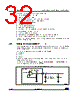
32 / 229 page 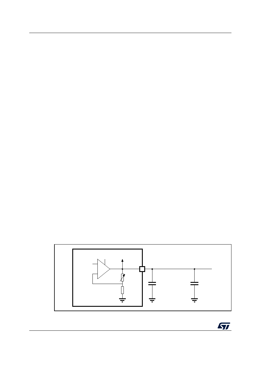 Functional overview STM32G473xB STM32G473xC STM32G473xE 32/229 DS12712 Rev 3 This digital interface supports the following features: • Up to two DAC output channels • 8-bit or 12-bit output mode • Buffer offset calibration (factory and user trimming) • Left or right data alignment in 12-bit mode • Synchronized update capability • Noise-wave generation • Triangular-wave generation • Saw tooth wave generation • Dual DAC channel independent or simultaneous conversions • DMA capability for each channel • External triggers for conversion • Sample and hold low-power mode, with internal or external capacitor • Up to 1 Msps for external output and 15 Msps for internal output The DAC channels are triggered through the timer update outputs that are also connected to different DMA channels. 3.20 Voltage reference buffer (VREFBUF) The STM32G473xB/xC/xE devices embed a voltage reference buffer which can be used as voltage reference for ADC, DACs and also as voltage reference for external components through the VREF+ pin. The internal voltage reference buffer supports three voltages: • 2.048 V • 2.5 V • 2.9 V An external voltage reference can be provided through the VREF+ pin when the internal voltage reference buffer is off. The VREF+ pin is double-bonded with VDDA on some packages. In these packages the internal voltage reference buffer is not available. Figure 3. Voltage reference buffer MSv40197V1 VREFBUF Low frequency cut-off capacitor DAC, ADC Bandgap + VDDA - 100 nF VREF+ |
|
Link URL |
| Does ALLDATASHEET help your business so far? [ DONATE ] |
About Alldatasheet | Advertisement | Contact us | Privacy Policy | Link to Datasheet | Link Exchange | Manufacturer List All Rights Reserved©Alldatasheet.com |
| Russian : Alldatasheetru.com | Korean : Alldatasheet.co.kr | Spanish : Alldatasheet.es | French : Alldatasheet.fr | Italian : Alldatasheetit.com Portuguese : Alldatasheetpt.com | Polish : Alldatasheet.pl | Vietnamese : Alldatasheet.vn Indian : Alldatasheet.in | Mexican : Alldatasheet.com.mx | British : Alldatasheet.co.uk | New Zealand : Alldatasheet.co.nz |
|
Family Site : ic2ic.com |
icmetro.com |
 New Zealand ▼
 English
 Chinese
 German
 Japanese
 Russian
 Korean
 Spanish
 French
 Italian
 Portuguese
 Polish
 Vietnamese
 Indian
 Mexican
 British
 New Zealand