|
Electronic Components Datasheet Search |
|
|
Electronic Components Datasheet Search |
|
M24C32-R Datasheet(PDF) 13 Page - STMicroelectronics |
|
|
|||||||||||||||||||||||||||||
M24C32-R Datasheet(HTML) 13 Page - STMicroelectronics |
|
|
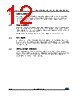
13 / 42 page 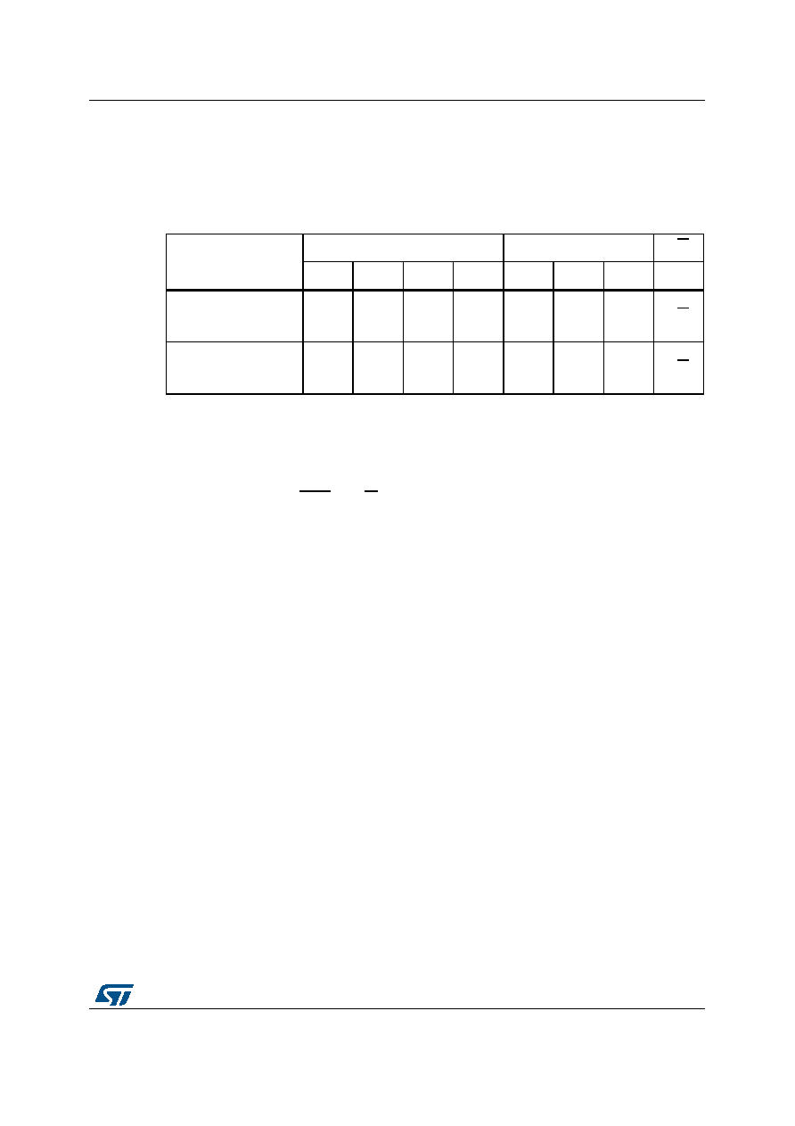 DocID4578 Rev 24 13/42 M24C32-W M24C32-R M24C32-F M24C32-X M24C32-DF Device operation 41 4.5 Device addressing To start communication between the bus master and the slave device, the bus master must initiate a Start condition. Following this, the bus master sends the device select code, shown in Table 2 (on Serial Data (SDA), most significant bit first). When the device select code is received, the device only responds if the Chip Enable address is the same as the value on its Chip Enable E2,E1,E0 inputs. The 8th bit is the Read/Write bit (RW). This bit is set to 1 for Read and 0 for Write operations. If a match occurs on the device select code, the corresponding device gives an acknowledgment on Serial Data (SDA) during the 9th bit time. If the device does not match the device select code, the device deselects itself from the bus, and goes into Standby mode. Table 2. Device select code Device type identifier(1) 1. The most significant bit, b7, is sent first. Chip Enable address(2) 2. E0, E1 and E2 are compared with the value read on input pins E0, E1,and E2. RW b7 b6 b5 b4 b3 b2 b1 b0 Device select code when addressing the memory array 1010 E2 E1 E0 RW Device select code when accessing the Identification page 1011 E2 E1 E0 RW |
|
Link URL |
| Does ALLDATASHEET help your business so far? [ DONATE ] |
About Alldatasheet | Advertisement | Contact us | Privacy Policy | Link to Datasheet | Link Exchange | Manufacturer List All Rights Reserved©Alldatasheet.com |
| Russian : Alldatasheetru.com | Korean : Alldatasheet.co.kr | Spanish : Alldatasheet.es | French : Alldatasheet.fr | Italian : Alldatasheetit.com Portuguese : Alldatasheetpt.com | Polish : Alldatasheet.pl | Vietnamese : Alldatasheet.vn Indian : Alldatasheet.in | Mexican : Alldatasheet.com.mx | British : Alldatasheet.co.uk | New Zealand : Alldatasheet.co.nz |
|
Family Site : ic2ic.com |
icmetro.com |
 New Zealand ▼
 English
 Chinese
 German
 Japanese
 Russian
 Korean
 Spanish
 French
 Italian
 Portuguese
 Polish
 Vietnamese
 Indian
 Mexican
 British
 New Zealand